For product information and a complete list of distributors, please go to our web site:
www.avagotech.com
Avago, Avago Technologies, and the A logo are trademarks of Avago Technologies in the United States and other countries.
Data subject to change. Copyright © 2005-2012 Avago Technologies. All rights reserved.
AV02-3426EN - April 30, 2012
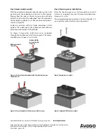
Figure 4 b. Secure the module to the base plate with two screws
Step 4. Encoder module assembly
With the encoder module part number side up, slip it into
position with the codewheel in the slot in the housing.
Moving from the side, as shown in Figure 4a, and being
careful not to contact the codewheel, seat the module on
the base plate guide posts. Its final position should be as
shown in Figure 4b.
Avoid any collision with the fragile codewheel, which
could result in damage to the codewheel and adversely
affect the performance of the encoder.
As shown in Figure 4b, install two screws (supplied)
through the module and into the base plate. The recom-
mended screw torque is 3.5-4.0 in-lbs.
Figure 4 a. Position the encoder module with the codewheel passing
through the slot
Module with the
part number side
facing up
Module guide posts,
two places
Figure 5. Housing cover assembly
Step 5.
Housing cover installation
Place the housing cover over the base plate and install
two screws (supplied) to secure. The recommended screw
torque
is 2-4
in-lbs.
The completed encoder assembly is shown in Figure 6. It is
now ready for cable attachment and operation.
Figure 6. Completed HEDC-5xxxx assembly


