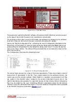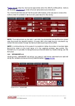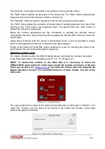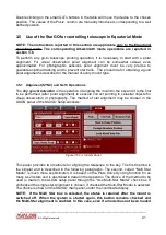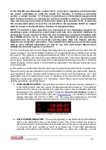
In this window it is possible to insert new names for the device connected to each of the
Aux ports. This name will appear in the above matrix. Also the gauge units defined in the
AUX Tab will be reported in the matrix for each device. In the following example the
“Steeldrive” port controls a Steeldrive focuser mounted in a C11 telescope, guide scope
focuser is connected to the Aux1 port and the Aux2 port controls a filter wheel.
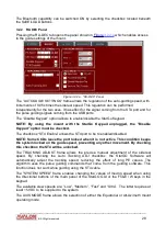
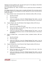
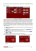
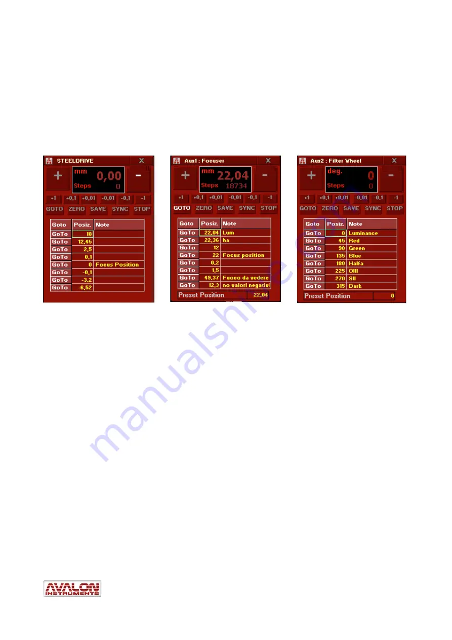
Double clicking on the name of a device in the matrix above will bring up one of three new
auxiliary windows to allow the insertion of the required parameters for motor control of the
selected device. The three windows
,
seen below, are very similar in appearance.
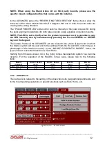
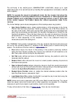
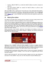
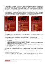
Figure 3.4.m: Steeldrive Panel
Figure 3.4.n: Aux1 Panel
Figure 3.4.o: Aux2 Panel
The positional values may be linear as, for example, focuser extraction or rotational as in
degrees of a filter wheel.
The five buttons in each window allow easy management of these parameters:
The GOTO button performs the repositioning of a device to the value introduced in
the display
;
The ZERO button is for zeroing out the display value
;
Clicking on the SAVE button will save the introduced parameters, otherwise these
will be lost when the StarGO system is exited
;
The SYNCH button will enable synchronization of the device position with the value
reported in the selected row of the table
;
The STOP will halt all the device motor movements in case of need.
The display will show the current values of the parameters, including the measurement
units.
The two +/- buttons enable manual movement of the related device in either of the two
directions in a continuous manner.
The six small buttons with the numbers -1, -0.1, -0.01, +0.01, +0.1, +1 will move the
associated device in a fixed value defined by the number in the button selected.
____________________________________________________________________
©
All Rights reserved
40


