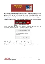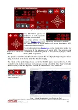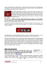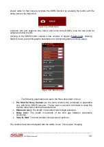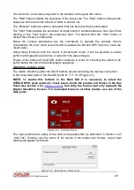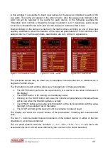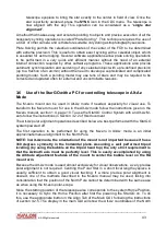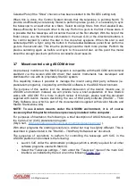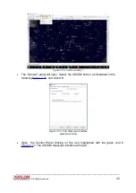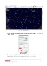
Double clicking on the small GoTo buttons in the table will move the device to the chosen
position. The values of the Posiz. column are manually introduced
,
corresponding to
a well
defined position.
3.5 Use of the StarGO for controlling telescope in Equatorial Mode
NOTE: The instructions reported in this section are applicable only to the Equatorial
operating mode. The corresponding Alt-Azimuth mode operations are reported in
section 3.6.
To perform any go-to telescope pointing operation, it is necessary to start with a polar
alignment. For visual observation polar alignment can be somewhat casual, even
approximated. For photographic sessions polar alignment must be very precise to
guarantee optimal tracking and to prevent star trails. The procedure for obtaining a good
polar alignment is described in the manual of every mount type.
3.5.1 Alignment (SYNC) and GoTo Operations
The
sky synchronization
is
the operation of aligning the mount to the sky and it is the first
to be performed (after polar alignment) to execute correct pointing to celestial objects for
visual observation or photography. The method of star alignment may be chosen in the
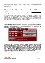
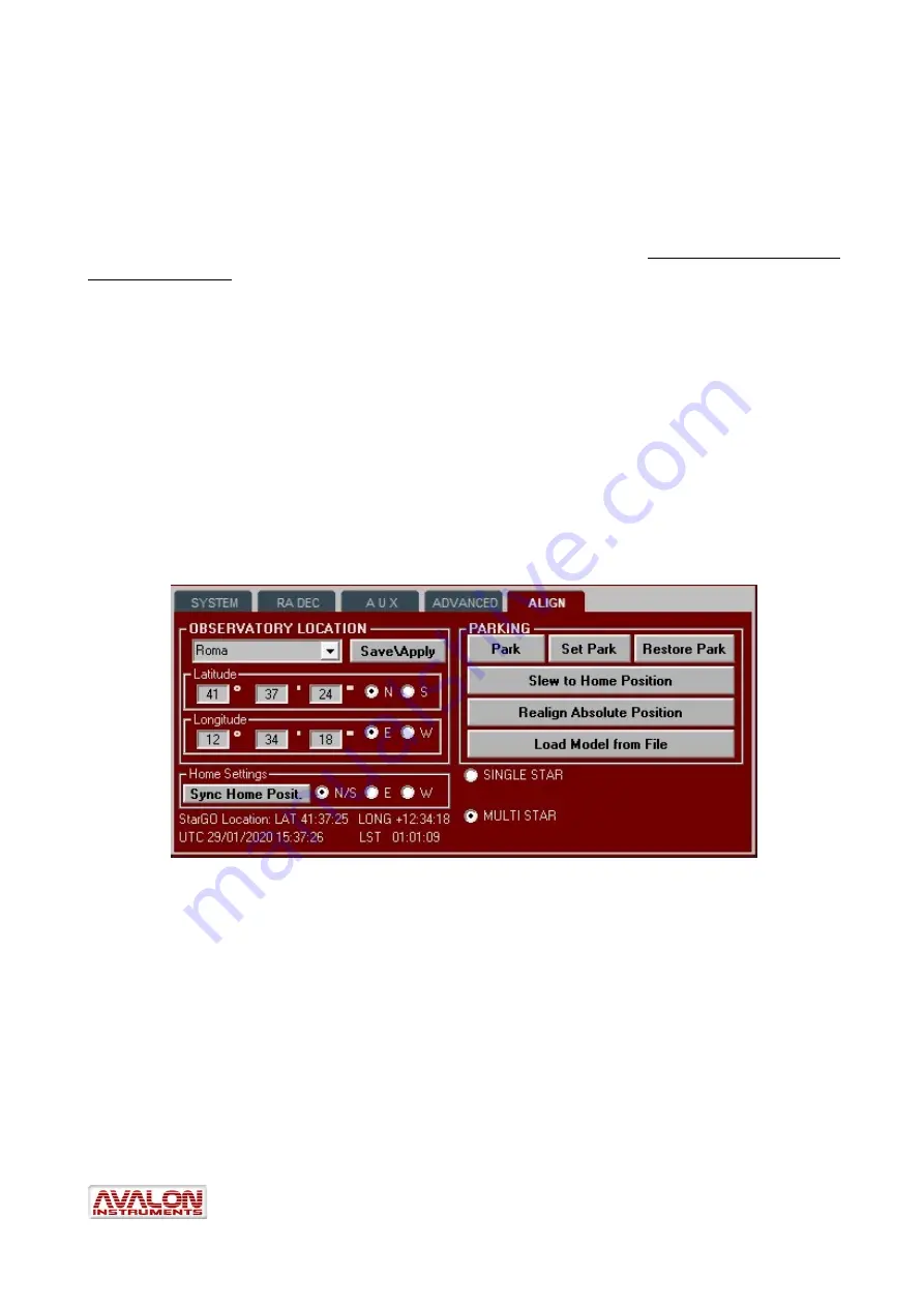
ALIGN panel of the StarGO setup windows:
This panel provides two methods for aligning the telescope to the sky. The first method is
the simpler and is described in the following paragraphs. The second, called “Multi Star
Model” is much more sophisticated. It is based on the Plate Solve Syncing function for as
many as 24 stars and is described in detail in the Appendix. The choice of the method to be
used is made in the ALIGN setup panel through the “Use Multi-Star Model” check box. If
unchecked the single star Alignment is chosen, if checked the Multi-Star Model is selected.
The choice is shown in the StarGO main panel, under the coordinate display.
NOTE: If the Multi Star box is selected, the status is retained after the mount is
switched off. When the system is started again, this button remains checked and
the Multi-Star alignment is enabled. In this case, even if a model has not been loaded
____________________________________________________________________
©
All Rights reserved
41
Figure 3.5.1a: ALIGN Panel

