background image

18


Installation  (for qualified installers only) 

© Travis Industries 

4151204 

100-01430 

Vent Connector Removal and Installation (continued) 


The vent connector slides back and disengages from the three tabs on top of the insert. 


Connect the flex vent (exhaust and intake) to the vent connector (use self-drilling screws or hose clamps). 


The vent connector may be removed.

When replacing, make sure the gasket 

under the connector remains in place.

This screw holds the 

connector in place.

1/4" Nutdriver

“I” Intake 

“E” Exhaust 

Summary of Contents for Radiant Plus Small Insert

Page 1: ...OLED NEVER ALLOW CHILDREN TO TOUCH GLASS A barrier designed to reduce the risk of burns from the hot viewing glass is provided with this appliance and shall be installed for the protection of children and other at risk individuals Report 0028GN101S Omni Test Laboratories Inc Portland Oregon ANSI Z21 88 2014 CSA 2 33 2014 Direct Vent Fireplace Insert Masonry or Factory Built Metal Wood Burning Fire...

Page 2: ... has the same serial number as yours The serial number is attached to the appliance near the gas control valve This serial number will be needed in case you require service of any type Model Radiant Plus Small Serial Number Purchase Date Purchased From Register your warranty online at traviswarranty com Or mail your warranty card to Travis Industries House of Fire 12521 Harbour Reach Dr Mukilteo W...

Page 3: ...d Installation 17 Vent Connector Removal and Installation continued 18 Surround Panel Installation 20 Glass Frame Removal and Installation 21 Glass Frame Removal and Installation continued 22 Face Installation 23 Log Installation 24 Rock Wool Placement 27 Ember Placement 27 Steps for Finalizing the Installation 28 Air Shutter Adjustment 29 Before You Begin 30 Location of Controls 30 Starting the P...

Page 4: ...d in Manufactured Housing only after the home is site located All exhaust gases must be vented outside the structure of the living area Combustion air is drawn from outside the living area structure The venting must not be connected to a chimney flue serving a separate solid fuel burning appliance Notify your insurance company before hooking up this fireplace The instructions in this manual must b...

Page 5: ... house how to shut gas off to the appliance and at the gas main shutoff valve The gas main shutoff valve is usually next to the gas meter or propane tank and requires a wrench to shut off A barrier designed to reduce the risk of burns from the hot viewing glass is provided with this appliance and shall be installed for the protection of children and other at risk individuals If the barrier becomes...

Page 6: ...ity in square feet 400 1 250 400 1 250 Maximum BTU Input Per Hour 25 000 25 000 Heating capacity will vary with floor plan insulation and outside temperature Dimensions Electrical Specifications for optional blower Blower Electrical Rating 120 Volts 60 Hz Max 0 55 Amps Fuel This heater is shipped in natural gas NG configuration but may be converted to use propane LP using the included conversion k...

Page 7: ...P All exhaust gases must be vented outside the structure of the living area Combustion air is drawn from outside the living area structure Notify your insurance company before hooking up this heater The requirements listed below are divided into sections All requirements must be met simultaneously The order of installation is not rigid the qualified installer should follow the procedure best suite...

Page 8: ... a bedroom Please be aware of the large amount of heat this appliance produces when determining a location Fireplace Sizing Minimum Height 19 75 502mm Minimum Width 27 686mm Minimum Depth 15 381mm Hearth Extension 0 0mm The gas line should be installed prior to installing the heater For tight fits under 28 see the section Removing the Vent Connector See Leveling Legs for details on leveling the he...

Page 9: ...d in certain cases The surround panels should not seal ventilation openings on the fireplace CAUTION Firebox floor removal is not covered under the appliance safety standard ANSI Z21 88 CSA 2 33 used in the safety certification of this appliance The safety certification does not apply to this method of installation Before installing the appliance using this method contact the Authority Having Juri...

Page 10: ...ppliance Plug the power cord into a grounded 120 Volt outlet do not remove the grounding pin The electrical connection may also be made using the optional Wiring Kit SKU 97200315 The appliance when installed must be electrically grounded in accordance with local codes or in the absence of local codes with the National Electrical Code ANSI NFPA 70 or the Canadian Electrical Code CSA C22 1 Loosen th...

Page 11: ... non combustible 33 839mm n Mantel combustible or non combustible 34 864mm for Max 12 Mantel 33 839mm for Max 4 Mantel x Hearth Extension 0 0mm The combustible area above the non combustible facing must not protrude more than 3 4 20mm from the facing If it does it is considered a mantel and must meet the mantel requirements listed in this manual Mantel Requirements The maximum mantel depth is 12 3...

Page 12: ...upply piping during any pressure testing of that system at test pressures in excess of 1 2 psig For pressures under 1 2 psig isolate the gas supply piping by closing the manual shutoff valve Leak test all gas line joints and the gas control valve prior to and after starting the heater This heater is designed either for natural gas or for propane but not for both Check the sticker on the top of the...

Page 13: ... and terminate above the chimney top Be careful not to crimp or rupture the liner when bending it into chimney offsets When installed the vent must meet all of the vent manufacturer s requirements Use the following vent 3 UL 441 or 1777 Gas Liner for Exhaust and Air Inlet Duravent Chimney Liner Termination use one of the two listed below Prairie Cap with Flashing included in kit shown above 3 3 Co...

Page 14: ...er and pilot Reduce the restrictor setting if this occurs If restrictor adjustment is required make sure to make the adjustment one step at a time Wait a minimum of 5 minutes after burner ignition to monitor flame quality Restrictor Adjustment To access the restrictor remove the baffle at the top of the firebox Loosen the 4 screws holding it in place then slide it forward and down to remove The re...

Page 15: ...n Secure the vent to the fireplace insert and termination kit using screws Vent Location Intake I 3 76mm Exhaust E 3 76mm Inlet Exhaust Approved Cap 3 76mm dia Gas Liner Flashing Inlet Exhaust Additional Coaxial Sections May Be Added support as needed Intake I 3 76mm Exhaust E 3 76mm Approx 12 305mm ...

Page 16: ...equires a minimum chimney cross section of 48 square inches Factory Built Metal Wood Burning Fireplace Inlet Exhaust Re Line Exhaust Only Re Line Direct Vent Cap either high wind or Prairie Recommended Block Off Plate must be non combustible metal insulation Prevents odors from chimney entering room 6 5 8 to 3 3 Colinear Adapter Flashing A block off plate must seal the intake to the chimney space ...

Page 17: ...move the vent connector and attach it to the flex vent see the instructions on the following page NOTE be careful of the anti seize on the connector it will stain clothing etc 3 Pull on the flex vent until the vent connector is at the same height as the insert Temporarily attach the flex vent to the top of the chimney leave extra slack 4 Slide the insert into place guiding the vent connector into ...

Page 18: ... slides back and disengages from the three tabs on top of the insert Connect the flex vent exhaust and intake to the vent connector use self drilling screws or hose clamps The vent connector may be removed When replacing make sure the gasket under the connector remains in place This screw holds the connector in place 1 4 Nutdriver I Intake E Exhaust ...

Page 19: ...1204 100 01430 The vent connector when hanging from the chimney may be grasped by reaching above the insert Carefully move the connector forward making sure all 3 tabs insert through the connector Secure the vent connector to the insert using the screw removed earlier ...

Page 20: ...38 96100552 Large 28 5 40 96100553 1 The insert should be in position with gas line and flue and intake connections attached but pulled out slightly to allow panel installation 2 Attach the surround panel to the insert as shown below Remove these 2 screws c a Attach the panel to the insert The 4 tabs on the panel fit into the 4 slots on the insert b Replace the 2 screws to secure the panel to the ...

Page 21: ...directions shown to the right a Glass Frame Lift the glass frame up and pull it forward to remove NOTE You may need to lift the glass frame while re attaching b Re Attaching the Glass Frame a Hang the glass frame on the firebox b While holding in place attach the upper latches follow the instructions to the right in reverse c Lift the glass frame slightly and attach the lower latches Twist 1 4 tur...

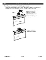
Page 22: ...atch is turned 1 8 turn when disengaged from the unit Follow the directions below to re install the latch if it comes loose Glass Hold the latch at an angle and insert it into the slot on the glass frame Note how the washer fits in front of the flange on the glass frame You will need to push slightly to get the latch to insert Once fully inserted turn the latch until it is is level Latch ...

Page 23: ...tection of children and other at risk individuals If the barrier becomes damaged the barrier shall be replaced with the manufacturer s barrier for this appliance The face includes the required barrier screen Make sure it is in place during operation 1 The insert should be in position with gas line and flue intake attached If using a surround panel it should be attached as well 2 Attach the face to...

Page 24: ...ry If using propane LP convert the appliance before installing the media see page 42 The burner must be correctly positioned before installing the media Make sure the burner is fully seated and the pilot is properly aligned See page 42 for details on burner removal Install the logs following the directions below Install the optional firebacks before installing the logs 1 The log stands are shipped...

Page 25: ...100 01430 3 The left log has two holes on the bottom Place the log so the holes fit over the two mounting studs on the left log stand 4 The right log has two holes on the bottom Place the log so the holes fit over the two mounting studs on the right log stand ...

Page 26: ...ce the log so the hole fits over the left pin on the rear log The front of the log rests on the left log see picture for orientation 6 The right cross log has one hole on the bottom Place the log so the hole fits over the right pin on the rear log The front of the log rests on the right log see picture for orientation ...

Page 27: ... method for applying the rock wool is to brush it on to the burner Compress a clump of rockwool between your thumb and forefinger Use a stiff brush to apply a thin layer of rockwool fibers onto the burner Do not use the entire bag of rockwool Use only a small amount and save the remainder Over use of rockwool will diminish the glow and may cause sooting or other adverse conditions Ember Placement ...

Page 28: ...d are required for operation 4 Synchronize the remote to the receiver and put the remote in manual mode a Install batteries into receiver b When red LED light flashes press any button on the remote c Red light will go out indicating the remote is synchronized to the receiver d Put the remote in Manual Mode press both buttons until thermostat icon thermometer disappears 5 Install firebacks if appli...

Page 29: ...flames should not contact the top of the firebox Check the flame on low position The flames should burn off of each burner hole If the heater does not work correctly contact your Travis dealer for a remedy 13 Give this manual to the home owner for future reference and fully explain operation of this heater Correct Flames should be blue at the base yellow orange on the top If the flames are too tal...

Page 30: ...the instructions may result in property damage bodily injury or even death Turn off the main gas supply to the appliance during appliance installation or maintenance During appliance installation or maintenance or in case of remote control malfunction turn off the main gas supply Location of Controls To access the gas control valve remove the face The location is shown below Gas Control Valve ...

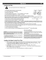
Page 31: ...ure the painted surfaces Fumes from the paint curing and oil burning off the steel will occur This is normal We recommend opening a window to vent the room Condensation may appear on the glass each time you start the heater this is normal Blue Flames will occur on the heater when it first comes on After fifteen minutes the flames will turn a more realistic yellow and orange color Verify the power ...

Page 32: ...32 Operation Travis Industries 4151204 100 01430 Remote Control Operation ...

Page 33: ...Operation 33 Travis Industries 4151204 100 01430 Remote Control Operation continued ...

Page 34: ...34 Operation Travis Industries 4151204 100 01430 Remote Control Operation continued ...

Page 35: ...Operation 35 Travis Industries 4151204 100 01430 Remote Control Operation continued ...

Page 36: ...trol Valve As the gas control valve is turned on and off and the flame height changed you will hear the flame height motor Optional Blower Snap Disk This part can produce a clicking sound as it turns the blower on and off The appliance may creak with change of temperature THIS IS NORMAL Pilot Assembly The pilot flame will make a slight whisper sound Optional Blower This heater has an optional blow...

Page 37: ...in place with hook and loop tape and a tab on the left side Remove the receiver from the insert and place it in front of the insert it is held in place with hook and loop tape Remove the battery cover on top of the receiver and install four new AA batteries into the receiver Replace the cover on the receiver and place it back into position Replace the heat shield note how the tab on the left side ...

Page 38: ...Check the media for sooting A small amount of soot along the bottom of the media is normal If excessive sooting is found the heater will require adjustment Contact your dealer 4 Inspect the burner and remove any debris Make sure the burner is not warped cracked or damaged Check the firebox and area around the pilot to make sure there is no warping or damage If any problem is found discontinue use ...

Page 39: ...Do not operate appliance with the glass front removed cracked or broken Replacement of the glass should be done by a licensed or qualified service person Contact your local Travis Industries Dealer for a Replacement Parts List Wiring Diagram Caution Label all wires prior to disconnection when servicing controls Wiring errors can cause improper and dangerous operation ...

Page 40: ...intake system is disconnected for servicing or any other reason it must be resealed and or reinstalled WARNING Improper installation adjustment alteration service or maintenance can cause injury or property damage Refer to the owner s information manual provided with this appliance For assistance or additional information consult a qualified installer service agency or the gas supplier VENTED GAS ...

Page 41: ...of components lack of proper and regular maintenance damage incurred while the appliance is in transit alteration or act of God 8 This 7 Year warranty excludes damage caused by normal wear and tear such as paint discoloration or chipping worn or torn gasketing corroded or cracked logs embers etc Also excluded is damage to the unit caused by abuse improper installation modification of the unit dril...

Page 42: ...opane Conversion Instructions Convert the appliance prior to installing the gas line to ensure proper gas use 1 Remove the glass frame Remove the logs if installed 2 Remove the two log stands 3 Remove the 2 screws holding the burner in place 4 Remove the burner and place it aside 1 4 Nutdriver ...

Page 43: ... a b 7 16 Wrench Natural Gas Orifice 020N 3way 018N 2way LP Propane Orifce 014LP 020N or 018N 014LP 1 2 Wrench Use a 9 16 wrench to secure the manifold while removing the orifice with a 1 2 wrench Screw the LP orifice until orifice protrudes 15 16 23 8mm indicating full insertion use wrench to secure manifold when re attaching orifice d Look here for the orifice identification Apply thread sealant...

Page 44: ... Install the LP propane low rate screw 1 2mm stamped 120 near the base make sure it screws in all the way Replace the cover plate and screws HINT Unscrew the rate screw until it becomes loose Then move it back and forth slightly until it moves to the side Then use needle nose pliers to remove the rate screw 1 4 Nutdriver LP Rate Screw 1 2mm Stamped 120 near the base 4mm 5 32 Hex Wrench ...

Page 45: ...not overtighten the conversion plug it is not a gas seal Carefully unsnap the plastic cap on the inward end of the conversion plug Rotate the plug 180 and re attach it to the conversion plug Screw the conversion plug back into the gas control valve do not overtighten the conversion plug 10 Replace the firebox components 11 Restore the appliance to the correct configuration Make the gas line connec...

Page 46: ... to the right Slide the rear fireback behind the baffle on top of the firebox then pivot it into place It rests on the shelf at the back of the firebox Remove the clips attached to the firebox ceiling both sides The clips have a keyhole slot It can be removed by loosening the screw and sliding the clip out a b MAKE SURE THE FULL BRICK IS AT THE TOP this allows the mortar lines to line up While hol...

Page 47: ... for qualified installers only 47 Travis Industries 4151204 100 01430 Optional Blower The optional blower is installed after the insert is installed and connected See the instructions included with the blower for details ...

Page 48: ...on Options 6 Installation Warnings 7 Leveling Legs 10 Location of Controls 30 Log Installation 24 LP Conversion Instructions 42 Maintaining Your Heater s Appearance 38 Normal Operating Odors 36 Normal Operating Sounds 36 Order of Installation 7 Packing List 7 Power Outages 36 Remote Control Operation 32 Replacement Parts List 39 Rock Wool Placement 27 Starting the Heater for the First Time 31 Star...

Reviews: