_____________________________________________________________________
©
All Rights reserved
26
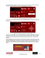
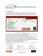
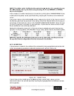
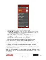
The above figure shows only a few of the mount parameters. The total number of the
parameters is normally of several tens. Their values depend on the software version, the
mount type and the custom settings. With the StarGO installation several default .mcf files
are copied in the StarGO folder, related to the Avalon Instrument mounts and to the
StarGO standalone kits available for supported mounts of other brands. Other configuration
files may be added by the user, containing different customized setups for the owner’s
mount(s), using the described Save button. The most suitable configuration file is uploaded
to the StarGO using the Load button.
4.2.2 RA DEC Panel
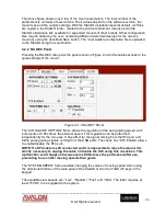
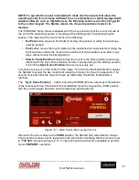
Pressing the RA-DEC tab opens the panel shown in Figure 4.3 which enables access to the
guide settings of the mount.
Figure 4.3 –“RA-DEC” Panel
The “AUTOGUIDE SETTING” frame allows the regulation of the auto-guiding speed, with
increments of 0.05x times the sidereal
speed. This regulation can be performed
independently for the two axes. It has effect for the signal coming from the ST4 port and
forthe pulse guiding signals coming from the USB ports. The check box “ST4 Enable” allows
to enable/disable the ST4 port.
NOTE: If a ST4 cable is still connected and it is impossible to move the mount, it is
strictly necessary to unplug the cable or disable the ST4 using this check box. This
malfunction event happens because some CCDs leave the port locked after use,
preventing to use other moving speeds then guide.
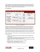
The “SYSTEM SPEED” frame enables changing the values of moving speed when using
the directional buttons of the main panel of the StarGO GUI or the Fn&E / W keys in the
keypad.
The available slew speeds are: “Low”, “Medium”, ”Fast” and “Ultra”. The latter requires at
least 15 VDC to be supplied to the system.


