_____________________________________________________________________
©
All Rights reserved
28
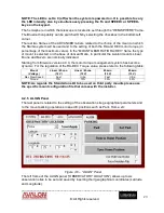
NOTE: The motors driven by the AUX 1 and AUX 2 ports are disconnected from the
power once they reach the due position. It means that in this state they do not absorb
any current but are not able to keep mechanical loads requiring an active effort.
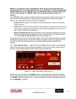
NOTE: In all three frames of this panel it is possible to define the number of decimal
digits that will be shown in the main panel or in the separate windows (see section
4.4). Furthermore, it is possible to change the Aux port denomination by double
clicking over the frame tab.
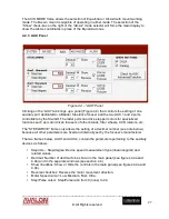
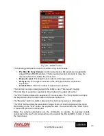
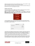
Fig- 4.4a – SHOW BUTTONS checked
…
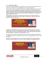
Fig. 4.4b -
…
and unchecked
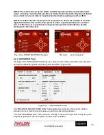
4.2.4 ADVANCED Panel
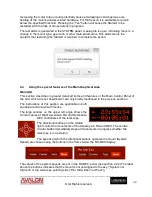
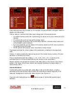
Clicking on the “ADVANCED” tab brings up a panel in which base parameters are selected
during the installation phase and rarely used thereafter. (Figure 4.5).
Figure 4.5 – “ADVANCED” Panel
The “REVERSE MOTOR DIRECTION” frame allows the inversion of the motor rotation
direction if one or both the mount axes are moving in the wrong direction.
The “POLAR FINDER LED” frame sets the intensity of the polar scope LED during the polar
alignment operations (for both types of polar scope available).


