_____________________________________________________________________
©
All Rights reserved
29
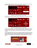
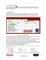
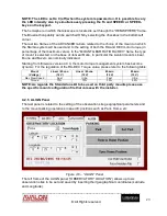
NOTE: The LED is set to 0 (off) when the system is powered on. It is possible to vary
the LED intensity also by simultaneously pressing the Fn and SPEED+ or SPEED-
keys on the keypad.
The hemisphere in which the telescope is located is set through the “HEMISPHERE” frame.
The Bluetooth capability can be switched ON by selecting the checkbox in the bottom-left
corner.
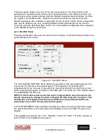
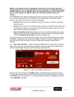
The last two frames of the ADVANCED tab are related to the choice of the mount on which
the StarGo system will be used and to the setting of both the RA and DEC motor torque (in
percentage of the maximum value). In the “MOUNT GEAR RATIO RA/DEC” frame the type
of mount is selected, on the base of its Gear Ratio, In particular the Avalon mounts Linear,
M-uno and M-zero are nominally indicated.
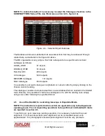
Starting from firmware version 4.0.0, the motor torque management system has become
dynamic. For the regulation of the RA-DEC Torque value, please refer to the following table:
Mount
(Voltage)
Linear / M-uno
(12 V)
Linear / M-uno
(15 V)
M-zero
(12 V)
M-zero
(15 V)
Max Slew Speed
Fast
Ultra
Fast
Ultra
Torque
70%
70%
50%
50%
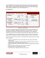
NOTE: As regards the Stand Alone kit to be used on third party mounts please use
the specific mount configuration file that comes with the installer.
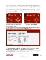
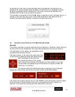
4.2.5 ALIGN Panel
The last panel is related to the setting of the observation site geographical parameters and
to the mount parking operations in specific positions such as Park, Home, etc.
Figure 4.6 – “ALIGN” Panel
The left frame of the ALIGN panel (“OBSERVATORY LOCATION”) allows up to six
observation sites to be set and saved by inserting their geographical coordinates (Latitude
and Longitude).


