background image

ENX-CDD User

’s Manual 

6 ENX-CDD User

’s Manual 


1.4 Manual Objectives 

This manual describes in details Avalue Technology ENX-CDD Single Board.   


We  have  tried  to  include  as  much  information  as  possible  but  we  have  not  duplicated 

information that is provided in the standard IBM Technical References, unless it proved to 

be necessary to aid in the understanding of this board. 


We strongly  recommend that  you  study  this manual  carefully  before  attempting  to  set  up 

ENX-CDD  series  or  change  the  standard  configurations.  Whilst  all  the  necessary 

information is available in this manual we would recommend that unless you are confident, 

you contact your supplier for guidance. 


If you have any suggestions or find any errors regarding this manual and want to inform us 

of these, please contact our Customer Service department with the relevant details. 


Summary of Contents for ENX-CDD

Page 1: ...E2047XCDD02R ENX CDD Intel Atom Cedar Trail Nano ITX Motherboard Intel D2550 or N2800 NM10 Chipset User s Manual 3rd Ed 25 January 2013 Copyright Notice Copyright 2013 Avalue Technology Inc ALL RIGHTS RESERVED ...

Page 2: ...er JS1 JS2 16 2 4 3 LCD Inverter connector INCN1 17 2 4 4 General Purpose I O JGPIO1 17 2 4 5 VGA connector JVGA1 18 2 4 6 Serial port 1 connector JCOM1 18 2 4 7 System Fan connector SFAN1 19 2 4 8 Speaker connector J3 19 2 4 9 Keyboard mouse connector JKB_MS1 20 2 4 10 Low Pin Count LPC 20 2 4 11 SATA AUX Board SATACON2 21 2 4 12 Reset connector J_RST 21 2 4 13 LVDS connector LVDS1 22 2 4 14 USB ...

Page 3: ...38 3 6 3 2 South bridge 39 3 6 4 Boot settings 40 3 6 5 Security 41 3 6 5 1 Administrator Password 41 3 6 5 2 User Password 41 3 6 6 Save Exit 42 3 6 6 1 Save Changes and Reset 42 3 6 6 2 Discard Changes and Reset 43 3 6 6 3 Restore Defaults 43 3 6 6 4 Save as User Defaults 43 3 6 6 5 Restore as User Defaults 43 4 Drivers Installation 44 4 1 Install Audio Driver For Realtek ALC661 HD Audio 45 4 2 ...

Page 4: ...ectric charges As a safety precaution use a grounding wrist strap at all times Place all electronic components in a static dissipative surface or static shielded bag when they are not in the chassis Always note that improper disassembling action could cause damage to the motherboard We suggest not removing the heatsink without correct instructions in any circumstance If you really have to do this ...

Page 5: ... ENX CDD User s Manual 5 1 3 Document Amendment History Revision Date By Comment 1st October 2012 Avalue Initial Release 2nd December 2012 Avalue Update Mechanical Drawing 3rd January 2013 Avalue Update Drivers Installation ...

Page 6: ... necessary to aid in the understanding of this board We strongly recommend that you study this manual carefully before attempting to set up ENX CDD series or change the standard configurations Whilst all the necessary information is available in this manual we would recommend that unless you are confident you contact your supplier for guidance If you have any suggestions or find any errors regardi...

Page 7: ...PU Onboard Intel Atom Processor D2550 1M Cache 1 86 GHz or Onboard Intel Atom Processor N2800 1M Cache 1 86 GHz BIOS AMI 16MBit SPI BIOS System Chipset Intel NM10 I O Chip Nuvoton NCT5577D System Memory One 204 pin DDR3 1066 1333MHZ SO DIMM socket up to 4GB Max Watchdog Timer Reset 1 to 255 sec min per step H W Status Monitor Monitoring temperature voltage and cooling fan status Auto throttling co...

Page 8: ...o Amplifier Realtek ALC105 3W Stereo Class D Audio Amplifier 1 x 4 pin Header Ethernet LAN Chip 1 x Realtek RT8111E PCIe Gigabit Ethernet Ethernet Interface 10 100 1000 Base Tx Gigabit Ethernet SIM card SIM card 1 x SIM Card socket SD card socket Realtek RTS5138 USB card reader controller support SD SDHC card Mechanical Environmental Power Type 12V DC in Operating Temp 0 60 C 32 140 F Storge Temp ...

Page 9: ...ENX CDD User s Manual ENX CDD User s Manual 9 1 6 Architecture Overview Block Diagram The following block diagram shows the architecture and main components of ENX CDD ...

Page 10: ...ENX CDD User s Manual 10 ENX CDD User s Manual 2 Hardware Configuration ...

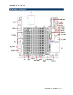
Page 11: ...ENX CDD User s Manual ENX CDD User s Manual 11 2 1 Product Overview ...

Page 12: ...ENX CDD User s Manual 12 ENX CDD User s Manual ...

Page 13: ...k floppy keyboard mouse USB etc except for flat panel A CRT monitor must be connected in order to change BIOS settings to support flat panel 4 Connect power supply to the board via the AC DC Adapter 5 Turn on the power 6 Enter the BIOS setup by pressing the delete key during boot up Use the Save Exit Restore Defaults feature 7 If TFT panel display is to be utilized make sure the panel voltage is c...

Page 14: ... when working with jumpers Connectors on the board are linked to external devices such as hard disk drives a keyboard or floppy drives In addition the board has a number of jumpers that allow you to configure your system to suit your application If you have any doubts about the best hardware configuration for your application contact your local distributor or sales representative before you make a...

Page 15: ...itch 1 00 mm SATACON2 SATA AUX Board 12 x 1 wafer pitch 1 00 mm JUSB1 USB connector 4 x 1 wafer pitch 1 25 mm F_MIC1 Mic in F_OUT1 Line out RJ1 LAN port IR1 CIR connector LED1 HDD LED PJ1 DC In JKB_MS1 Keyboard mouse connector 3 x 2 wafer pitch 2 54 mm F_USB1 USB connector1 F_USB2 USB connector2 F_USB3 USB connector3 INCN1 LCD Inverter connector 5 x 1 header pitch 2 54 mm SFAN1 System Fan connecto...

Page 16: ...er s Manual 2 4 Setting Jumpers Connectors 2 4 1 LVDS voltage JP1 Default VCC5 VCC3 Pin Define 1 2 VCC3 2 3 VCC5 2 4 2 mSATA Mini PCIe function Jumper JS1 JS2 Default MINIPCIE M SATA Pin Pin Define 1 3 2 4 M SATA 3 5 4 6 MINIPCIE JS1 JS2 ...

Page 17: ...Manual ENX CDD User s Manual 17 2 4 3 LCD Inverter connector INCN1 Signal PIN 5V 5 PWM 4 BKL_EN 3 GND 2 12V 1 2 4 4 General Purpose I O JGPIO1 Signal PIN PIN Signal GND 8 7 GND GPIO 6 5 GPIO GPIO 4 3 GPIO 3 3V 2 1 5V ...

Page 18: ...Manual 2 4 5 VGA connector JVGA1 Signal PIN PIN Signal GND 1 2 RED GND 3 4 GREEN GND 5 6 BLUE HSYNC 7 8 VSYNC DDC_DATA 9 10 DDC_CLK 2 4 6 Serial port 1 connector JCOM1 Signal PIN PIN Signal DCD 1 2 RXD TXD 3 4 DTR GND 5 6 DSR RTS 7 8 CTS RI 9 ...

Page 19: ...ENX CDD User s Manual ENX CDD User s Manual 19 2 4 7 System Fan connector SFAN1 Signal PIN Ground 1 12V 2 RPM 3 Control 4 2 4 8 Speaker connector J3 Signal PIN INTSPL 1 INTSPL 2 INTSPR 3 INTSPR 4 ...

Page 20: ...e connector JKB_MS1 Signal PIN PIN Signal MS_CLK 1 2 MS_DATA KB_CLK 3 4 KB_DATA VCC 5 6 GND Note The KB Mouse cable is not included 2 4 10 Low Pin Count LPC Signal PIN PIN Signal LPC_DATA3 1 2 3V LPC_DATA2 3 4 PLC_RESET LPC_DATA1 5 6 FPAME LPC_DATA0 7 8 CLK_33M GND 9 ...

Page 21: ...nual ENX CDD User s Manual 21 2 4 11 SATA AUX Board SATACON2 Note To SATA AUX board Signal PIN NC 1 5V 2 5V 3 5V 4 GND 5 GND 6 RXP 7 RXN 8 GND 9 TXN 10 TXP 11 GND 12 2 4 12 Reset connector J_RST Signal PIN Reset 1 GND 2 ...

Page 22: ...rd LVDS connector CSI 1171 30 Matting connector KB901 B30H Signal PIN PIN Signal VDD 30 29 VDD VDD 28 27 VDD DDC_CLK 26 25 GND DDC_DATA 24 23 DATA3 GND 22 21 DATA3 CLKN 20 19 GND CLKP 18 17 DATA2 GND 16 15 DATA2 GND 14 13 GND GND 12 11 GND DATA1 10 9 DATA0 DATA1 8 7 DATA0 GND 6 5 GND GND 4 3 PWM GND 2 1 GND ...

Page 23: ...ENX CDD User s Manual ENX CDD User s Manual 23 2 4 14 USB connector JUSB1 Signal PIN 5VSB 1 DATAN 2 DATAP 3 GND 4 2 4 15 Battery connector BAT1 Signal PIN BAT 1 GND 2 ...

Page 24: ...X CDD User s Manual 2 4 16 PCIE signal selector J_PCIE Signal PIN RXN 14 RXP 13 GND 12 TXN 11 TXP 10 GND 9 CLKP 8 CLKN 7 RESET 6 WAKE 5 5VSB 4 5VSB 3 GND 2 3 3V 1 Note For Customized add on card the expansion card is not included ...

Page 25: ...ENX CDD User s Manual ENX CDD User s Manual 25 3 BIOS Setup ...

Page 26: ...rol over to the operating system While the BIOS is in control the Setup program can be activated in one of two ways By pressing Del immediately after switching the system on or By pressing the Del key when the following message appears briefly at the bottom of the screen during the POST Power On Self Test Press DEL to enter setup F11 to popup menu If the message disappears before you respond and y...

Page 27: ... not save changes into NVRAM Status Page Setup Menu and Option Page Setup Menu Exit current page and return to the pervious page or Main Menu key Increase the numeric value or make changes key Decrease the numeric value or make changes F1 key General help only for Status Page Setup Menu and Option Page Setup Menu F2 key Previous Values F9 key Optimized Defaults F10 key Save and Exit Navigating Thr...

Page 28: ...our computer no longer is able to boot the AMI BIOS supports an override to the NVRAM settings which resets your system to its defaults The best advice is to only alter settings which you thoroughly understand To this end we strongly recommend that you avoid making any changes to the chipset defaults These defaults have been carefully chosen by both AMI and your systems manufacturer to provide the...

Page 29: ...ppear on the screen The Main Menu allows you to select from several setup functions and exit choices Use the arrow keys to select among the items and press Enter to accept and enter the sub menu 3 6 1 Main Menu This section allows you to record some basic hardware configurations in your computer and set the system clock ...

Page 30: ...ate option to set the system date Manually enter the day month and year 3 6 1 4 System Time Use the system time option to set the system time Manually enter the hours minutes and seconds Note BIOS setup screens shown in this chapter are for reference only and may not exactly match what you see on your screen Visit the Avalue website www avalue com tw to download the latest product and BIOS informa...

Page 31: ... other system devices for basic operation through the following sub menus 3 6 2 1 ACPI Settings You can use this item to set up ACPI Configuration Item Options Description Enable Hibernation Disabled Enabled Default Enables or Disables System ability to Hibernate OS S4 Sleep State This option may be not effective with some OS ...

Page 32: ...Item Options Description Hyper Threading Disabled Enabled Default Enabled for Windows XP and Linux OS optimized for Hyper Threading Technology and Disabled for other OS OS not optimized for Hyper Threading Technology Execute Disable Bit Disabled Enabled Default XD can prevent certain classed of malicious buffer overflow attacks when combined with a supporting OS Windows Server 2003 SP1 Windows XP ...

Page 33: ...led Azalia Controller USB Function Enabled Default Disabled Enable Disable USB Function USB 2 0 EHCI Support Enabled Default Disabled Enable or Disable USB 2 0 EHCI Support LAN Controller Enabled Default Disabled Enable or Disable OnChip NIC Controller Launch PXE OpROM Enabled Disabled Default Enable or Disable Boot Option for Legacy Network Devices ...

Page 34: ...I Hand Off Enabled Disabled Default This is a workaround for OSes without EHCI hand off support The EHCI ownership change should be claimed by EHCI driver USB transfer time out 1sec 5sec 10sec 20sec Default The time out value for Control Bulk and Interrupt transfers Device reset time out 10sec 20sec Default 30sec 40sec USB mass storage device Start Unit command time out Device power up delay Auto ...

Page 35: ...is item to set up or change the Super IO configuration for FDD controllers parallel ports and serial ports Item Options Description Serial Port 0 Configuration Set Parameters of Serial Port0 COMA WatchDogTimer Enabled Disabled Default WatchDogTimer Setting 3 6 2 5 1 Serial Port 0 Configuration ...

Page 36: ...able Serial Port COM Change Settings Auto Default IO 3F8h IRQ 4 IO 3F8h IRQ 3 4 5 6 7 9 10 11 12 IO 2F8h IRQ 3 4 5 6 7 9 10 11 12 Select an optimal setting for Super IO device 3 6 2 6 W83627UHG HW Monitor The H W Monitor shows the operating temperature fan speeds and system voltages 3 6 2 7 Power Management Configuration ...

Page 37: ...ystem from S3 S5 by LAN Restore AC Power Loss Power Off Power On Last State Default Select AC power state when power is re applied after a power failure Wake system with Fixed Time Disabled Default Enabled Enable or disable System wake on alarm event When enabled System will wake on the hr min sec specified Wake up Day 0 31 Select 0 31 Note Enter 0 for everyday Wake up hour 0 23 Select 0 23 For ex...

Page 38: ...IGD Configuration Item Option Description IGFX Boot Type VBIOS Default Default CRT LFP EFP CRT LFP CRT EFP LFP EFP Select the Video Device which will be activated during POST This has no effect if external graphics present Active LFP Disabled Enable LVDS Default Enable or Disable LVDS ...

Page 39: ...ight Control Support VBIOS Default Default BLC BIA Disabled BLC Enabled Backlight Control Configuration 3 6 3 2 South bridge Item Option Description SATA Controller s Disabled Enabled Default SATA Ports 0 3 Device Names if Present and Enabled Configure SATA as IDE AHCI Default Select a configuration for SATA Controller Port0 Speed Limit No Limit Default GEN1 Rate GEN2 Rate Select Port0 AHCI Speed ...

Page 40: ...Setup Prompt Timeout 1 65535 Number of seconds to wait for setup activation key 65535 0xFFFF means indefinite waiting Bootup NumLock State On Default Off Select the keyboard NumLock state Quiet Boot Enabled Disabled Default Enables or disables Quiet Boot option Fast Boot Enabled Default Disabled Enables or disables boot with initialization of a minimal set of devices required to launch active boot...

Page 41: ...limits access to the BIOS setup program and is only asked for when entering the BIOS setup program By default no password is specified 3 6 5 2 User Password This setting specifies a password that must be entered to access the BIOS Setup Utility or to boot the system If only the User s password is set then this is a power on password and must be entered to boot or enter the BIOS setup program In th...

Page 42: ...NX CDD User s Manual 42 ENX CDD User s Manual 3 6 6 Save Exit 3 6 6 1 Save Changes and Reset Any changes made to BIOS settings are stored in NVRAM The setup program then exits and reboots the controller ...

Page 43: ...the factory default This option is useful if the controller exhibits unpredictable behavior due to an incorrect or inappropriate BIOS setting 3 6 6 4 Save as User Defaults This option saves a copy of the current BIOS settings as the User Defaults This option is useful for preserving custom BIOS setup configurations 3 6 6 5 Restore as User Defaults This option restores all BIOS settings to the user...

Page 44: ...CDD User s Manual 44 ENX CDD User s Manual 4 Drivers Installation Note Installation procedures and screen shots in this section are for your reference and may not be exactly the same as shown on your screen ...

Page 45: ...lue s products automatically If not locate Index htm and choose the product from the menu left or link to Driver_Audio ENX CDD_Audio Note The installation procedures and screen shots in this section are based on Windows 7 operation system If the warning message appears while the installation process click Continue to go on Step1 Click Yes to Install Step 2 Select Yes to restart computer ...

Page 46: ... s products automatically If not locate the folder HTML and choose the product from the targeted folder Note The installation procedures and screen shots in this section are based on Windows 7 operating system Step 1 Locate Driver_Chipset ENX CDD_Chipset Step 4 Select Next to continue installation Step 2 Select Next to start setup Step 5 Select Finish to complete Installation Step 3 Select Yes to ...

Page 47: ...locate the folder HTML and choose the product from the targeted folder Note The installation procedures and screen shots in this section are based on Windows 7 operating system Step 1 Locate VGA ENX CDD_Graphics Step 4 Select Next to continue installation Step 2 Select Next to start setup Step 5 Select Next to continue installation Step 3 Select Yes to the next step Step 6 Select Finish to complet...

Page 48: ...the index page of Avalue s products automatically If not locate Index htm and choose the product from the menu left or link to Driver_Network ENX CDD_LAN Note The installation procedures and screen shots in this section are based on Windows 7 operation system Step 3 Click Finish to complete setup Step 1 Click Next to Install Step 2 Click Install to begin the installation ...

Page 49: ... locate the folder HTML and choose the product from the targeted folder Note The installation procedures and screen shots in this section are based on Windows 7 operating system Step 1 Locate Utility ENX CDD_AHCI Step 4 Select Next to continue installation Step 2 Select Next to start setup Step 5 Select Next to continue installation Step 3 Select Yes to the next step Step 6 Select Finish to comple...

Page 50: ... show the index page of Avalue s products automatically If not locate Index htm and choose the product from the menu left or link to Utility Cardreader Note The installation procedures and screen shots in this section are based on Windows 7 operation system Step 3 Click Finish to complete setup Step 1 Preparing Setup Step 2 Installation ...

Page 51: ...page of Avalue s products automatically If not locate Index htm and choose the product from the menu left or link to Utility CIR Note The installation procedures and screen shots in this section are based on Windows 7 operation system Step 3 Click Finish to complete setup Step 1 Click Next to Install Step 2 Click Install to begin the installation ...

Page 52: ...ENX CDD User s Manual 52 ENX CDD User s Manual 5 Mechanical Drawing ...

Page 53: ...ENX CDD User s Manual ENX CDD User s Manual 53 Unit mm ...

Page 54: ...ENX CDD User s Manual 54 ENX CDD User s Manual Unit mm ...

Reviews: