background image


M

M

X

X

9

9

6

6

5

5

G

G

M

M

E

E


U

U

S

S

E

E

R

R

S

S


M

M

A

A

N

N

U

U

A

A

L

L


P

P

A

A

G

G

E

E


|

|


2

2

9

9


Chapter 3 


BIOS Setup 


This chapter provides information on the BIOS Setup program and allows 
you to configure the system for optimum use.  You may need to run the 
Setup program when:  


   An error message appears on the screen during the system booting 

up, and requests you to run SETUP.   
 

  You want to change the default settings for customized features. 


Summary of Contents for MX965GME

Page 1: ...Avalue Technology Inc MX965GME Intel Core 2 Duo Mini ITX Mainboard Users Manual 1st Edition 8 November 2007...

Page 2: ...PERATED IN A COMMERCIAL ENVIRONMENT THIS EQUIPMENT GENERATES USES AND CAN RADIATE RADIO FREQUENCY ENERGY AND IF NOT INSTALLED AND USED IN ACCORDANCE WITH THE INSTRUCTION MANUAL MAY CAUSE HARMFUL INTER...

Page 3: ...RITTEN APPROVAL OF Avalue Technology Inc As used herein 1 Life support devices or systems are devices or systems which a are intended for surgical implant into body or b support or sustain life and wh...

Page 4: ...le to be easily solved over the phone In addition free technical support is available from Avalue s engineers every business day We are always ready to give advice on application requirements or speci...

Page 5: ...ing to the cost of replacement materials service time and freight Please consult your dealer for more details If you think you have a defective product follow these steps 1 Collect all the information...

Page 6: ...isclaimer 3 Life Support 3 Technical Support 4 Product Warranty 5 Chapter 1 Product Overview Specifications 8 Layout 10 Chapter 2 Hardware Setup Component Location 12 CPU 13 Memory 14 Power Supply 15...

Page 7: ...965 ICH8M controllers for optimal system efficiency the MX965GME accommodates the latest Intel Core 2 Duo Celeron M 5XX series processors in Socket P and supports two 240 pin 533 667MHz DDRII DIMM to...

Page 8: ...8M chipset Memory DDR2 533 667 SDRAM 4GB Max 2 DDR2 DIMM slots 240pin 1 8V LAN Supports 2 Gb Ethernet by Intel 82573L 82566DC Audio HDA Codec by Realtek ALC888 7 1 channel Compliant with Azalia 1 0 sp...

Page 9: ...LVDS connector 1 TV out connector 1 digital I O connector 16GPIO 1 serial port connector 1 front panel connector Expansion 1 PCI Express x4 slot optional 1 Mini PCI E slot 1 PCI 32 bit 33MHz slot 1 C...

Page 10: ...M M X X 9 9 6 6 5 5 G G M M E E U U S S E E R R S S M M A A N N U U A A L L P P A A G G E E 1 10 0...

Page 11: ...e information about hardware setup procedures While doing the installation be careful in holding the components and follow the installation procedures For some components if you install in the wrong o...

Page 12: ...G M M E E U U S S E E R R S S M M A A N N U U A A L L P P A A G G E E 1 12 2 MX965GME JAUD2 JAMP1 PCI 1 JSPI2 J4 J6 F_USB1 F_USB2 J7 JCASE1 IDE1 COM2 JLPT1 JCF_SEL1 SATA 1 2 ATX Power SYS FAN CPU FAN...

Page 13: ...ce the CPU on top of the socket Make sure to align the gold arrow on the CPU with the arrow key on the socket 3 Push the CPU down until its pins securely fit into the socket 4 On the front end of the...

Page 14: ...y module has only one notch on the center and will only fit in the right orientation 2 Insert the memory module vertically into the DIMM slot Then push it in until the golden finger on the memory modu...

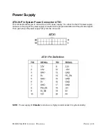
Page 15: ...r ATX1 This connector allows you to connect to an ATX power supply To connect to the ATX power supply make sure the plug of the power supply is inserted in the proper orientation and the pins are alig...

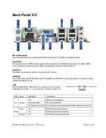
Page 16: ...at sends receives 16 bytes FIFOs You can attach a serial mouse or other serial devices directly to the connector VGA Port The DB15 pin female connector is provided for monitor USB Port The USB Univers...

Page 17: ...or different audio sound effects Line In Blue Line In Side Surround Out in 7 1 channel mode is used for external CD player tape player or other audio devices Line Out Green Line Out is a connector for...

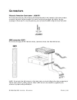
Page 18: ...The system will record this status and show a warning message on the screen To clear the warning you must enter the BIOS utility and clear the record IDEConnector IDE1 This connector supports IDE hard...

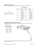
Page 19: ...ned to connect the General Purpose Input Output GPIO peripheral module Serial ATA II Connector SATA1 SATA2 This connector is a high speed Serial ATA II interface port Each connector can connect to one...

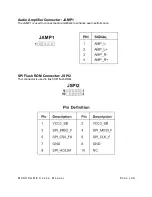
Page 20: ...E R R S S M M A A N N U U A A L L P P A A G G E E 2 20 0 Audio Amplifier Connector JAMP1 The JAMP1 is used to connect audio amplifiers to enhance audio performance SPI Flash ROM Connector JSPI2 This...

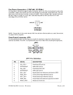
Page 21: ...s Ground and should be connected to GND If the mainboard has a System Hardware Monitor chipset on board you must use a specially designed fan with speed sensor to take advantage of the CPU fan control...

Page 22: ...of TV Out connectors S Video and RCA Composite connectors Select the appropriate one to connect the standard television or the HDTV High Definition Television NOTE Please note that the TV Out bracket...

Page 23: ...G M M E E U U S S E E R R S S M M A A N N U U A A L L P P A A G G E E 2 23 3 LVDS Flat Panel Connector JLVDS1 The LVDS Low Voltage Differential Signal connector provides a digital interface typically...

Page 24: ...B Connector F_USB1 F_USB2 This connector compliant with Intel I O Connectivity Design Guide is ideal for connecting high speed USB interface peripherals such as USB HDD digital cameras MP3 players pri...

Page 25: ...ns port that sends receives 16 bytes FIFOs You can attach a serial device to it through the optional serial port bracket Parallel Port Connector JLPT1 The mainboard provides a 26 pin header for connec...

Page 26: ...f the onboard serial ports Clear CMOS Jumper JBAT1 There is a CMOS RAM onboard that has a power supply from external battery to keep the data of system configuration With the CMOS RAM the system can a...

Page 27: ...t supports LAN card SCSI card USB card and other add on cards that comply with PCI specifications PCI Interrupt Request Routing The IRQ acronym of interrupt request line and pronounced I R Q are hardw...

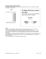
Page 28: ...support up to 2 IDE devices without CF device or 1 IDE device with 1 CF device If you install two IDE devices you must configure the second drive to Slave mode by setting its jumper Refer to the hard...

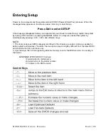
Page 29: ...This chapter provides information on the BIOS Setup program and allows you to configure the system for optimum use You may need to run the Setup program when An error message appears on the screen dur...

Page 30: ...and On or pressing the RESET button You may also restart the system by simultaneously pressing Ctrl Alt and Delete keys NOTE 1 The items under each BIOS category described in this chapter are under c...

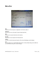
Page 31: ...view appears to the left of certain fields that means a sub menu can be launched from this field A sub menu contains additional options for a field parameter You can use arrow keys to highlight the f...

Page 32: ...up the items of special enhanced features Boot Use this menu to specify the priority of boot devices Security Use this menu to set supervisor and user passwords Chipset This menu controls the advance...

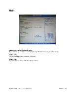
Page 33: ...N N U U A A L L P P A A G G E E 3 33 3 Main AMI BIOS Processor System Memory These items show the firmware and hardware specifications of your system Read only System Time The time format is Hour Minu...

Page 34: ...M M X X 9 9 6 6 5 5 G G M M E E U U S S E E R R S S M M A A N N U U A A L L P P A A G G E E 3 34 4 Advanced CPU Configuration These items show the advanced specifications of your CPU Read only...

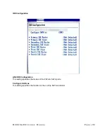
Page 35: ...E E R R S S M M A A N N U U A A L L P P A A G G E E 3 35 5 IDE Configuration ATA IDE Configuration This setting specifies the modes of the PATA SATA ports Configure SATA as This setting specifies the...

Page 36: ...uses Logical Block Addressing to be used in place of Cylinders Heads and Sectors Block Multi Sector Transfer Any selection except Disabled determines the number of sectors transferred per block PIO Mo...

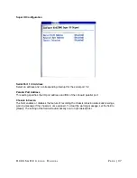
Page 37: ...serial port 1 2 Parallel Port Address This setting specifies the I O port address and IRQ of the onboard parallel port Chassis Intrusion The field enables or disables the feature of recording the cha...

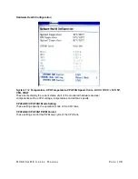
Page 38: ...re CPUFAN Speed Vcore AVCC 3VCC 12V 5V VSB VBAT These items display the current status of all of the monitored hardware devices components such as CPU voltage temperatures and all fans speeds CPUFAN0...

Page 39: ...de is a low power state In this state no system context is lost CPU or chipset and hardware maintains all system context S3 STR The S3 sleep mode is a lower power state where the information of system...

Page 40: ...controls the operation of the power button Resume On LAN This field specifies whether the system will be awakened from power saving modes when activity or input signal of onboard LAN is detected Resu...

Page 41: ...er and extend battery life Intel Robson technology is poised to eliminate many of the bottlenecks associated with HDD latency By enabling the majority of application workload to be written and read fr...

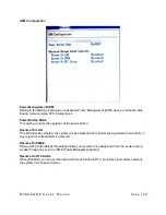
Page 42: ...R R S S M M A A N N U U A A L L P P A A G G E E 4 42 2 Remote Access Configuration Remote Access This field allows you to Enabled or Disabled Remote Access for console redirection via serial ports Set...

Page 43: ...ols the Trusted Platform Module TPM designed by the Trusted Computing Group TCG TPMs are special purpose integrated circuits ICs built into a variety of platforms to enable strong user authentication...

Page 44: ...operating system that does not support or have any USB 1 1 2 0 driver installed such as DOS and SCO Unix USB 2 0 Controller Mode This setting specifies the operation mode of the onboard USB 2 0 contr...

Page 45: ...M M X X 9 9 6 6 5 5 G G M M E E U U S S E E R R S S M M A A N N U U A A L L P P A A G G E E 4 45 5 Boot Boot Settings Configuration...

Page 46: ...powered on Setting to Off will allow users to use the arrow keys on the numeric keypad PS 2 Mouse Support Select Enabled if you need to use a PS 2 interfaced mouse in the operating system Wait For F1...

Page 47: ...e chassis instruction function Select Reset to clear the chassis instruction status Boot Device Priority 1st Boot Device The items allow you to set the sequence of boot devices where BIOS attempts to...

Page 48: ...G E E 4 48 8 Removable Drives 1st Drive This setting allows users to set the priority of the removable devices First press Enter to enter the sub menu Then you may use the arrow keys to select the des...

Page 49: ...sor Password Change Supervisor Password Supervisor Password controls access to the BIOS Setup utility These settings allow you to set or change the supervisor password User Password Change User Passwo...

Page 50: ...M M X X 9 9 6 6 5 5 G G M M E E U U S S E E R R S S M M A A N N U U A A L L P P A A G G E E 5 50 0 Chipset...

Page 51: ...ics card is present the motherboard boots up using that card Otherwise it defaults to the onboard graphics processor PEG Force X1 This BIOS feature allows you to convert a PCI Express X4 slot into a P...

Page 52: ...this BIOS feature to DVMT Mode for maximum performance Setting it to DVMT Mode ensures that system memory is dynamically allocated for optimal balance between graphics and system performance DVMT FIXE...

Page 53: ...ny USB 2 0 driver installed such as DOS and SCO Unix GbE Controller This setting disables enables the onboard Gigabit Ethernet controller GbE LAN Boot When Enabled the BIOS attempts to boot from a LAN...

Page 54: ...Exit Abandon all changes and exit the Setup Utility Discard Changes Abandon all changes and continue with the Setup Utility Load Optimal Defaults Use this menu to load the default values set by the m...

Page 55: ...M M X X 9 9 6 6 5 5 G G M M E E U U S S E E R R S S M M A A N N U U A A L L P P A A G G E E 5 55 5...

Reviews: