background image

Operating instructions  


Avant 850 


76 


 . 


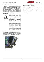
OptiDrive® 

The 850 loaders are equipped with the efficient 
Avant OptiDrive

®

 hydraulic drive system as standard.  

The system is designed for optimal hydraulic oil flow, 
which helps to conserve energy by minimising 
losses. This is achieved with the use of integrated 
high efficiency Avant valve blocks and EO3 type 
hose fittings. 


.. 


When you want to have a high pulling force: 

1.


Choose low speed range 

2.


Use high engine rpm 

3.


Press the drive pedal only lightly to select slow 
drive speed. This way the full output of the 
hydraulic system and the engine can be used 
for high pulling force. 

If the engine is overloaded while pushing, the 
pedal shouldn't be pressed further. Instead, use 
higher engine revs and push the pedal only a 
little. 


Summary of Contents for Avant 850

Page 1: ...English Operator s Manual 2020 A441827EN 2020 1 2020 www avanttecno com...

Page 2: ...57 Counterweights 58 Extra auxiliary hydraulics outlets front and rear 61 Seat Seat belt and seat adjustments 63 Lights 66 Cabs optional extra 68 OPERATING INSTRUCTIONS 71 Starting the loader 72 Ignit...

Page 3: ...tant safety information in this manual It warns of an immediate hazard that could cause serious personal injury to yourself or others near the equipment The safety alert symbol by itself and with rela...

Page 4: ...from your Avant dealer Remember also to give this Manual to the new owner when the loader changes ownership Manuals of attachments DANGER Attachments can create significant risks that are not covered...

Page 5: ...rk platform Different jobs require different attachments and it is not allowed to handle any loads or materials without any attachment fitted The loader must not be used in underground or tunneling wo...

Page 6: ...optional equipment is subject to change Some options may preclude the installation and use of some other option or options Check with your Avant dealer for more information Versions of this manual Av...

Page 7: ...n this manual is excluded 3 Avant Tecno Oy accepts no responsibility for interruption to working or any other consequential losses resulting from any failure of the product 4 Only Avant Tecno Oy appro...

Page 8: ...areful and deliberate movements Avoid abrupt movements when handling the load in order to prevent the load from falling and to keep the machine stable 7 Keep away from the danger zone of the lifted bo...

Page 9: ...er unexpectedly due to loss of stability mechanical fault or if another person operates the controls of the loader leading to crushing hazard The attachment or the loader are not intended to be left t...

Page 10: ...ng hazards Keep your head hands and feet inside the loader Be especially careful while you drive near walls and trees Keep your hands on steering wheel and joystick CAUTION Avoid pinching hazard for l...

Page 11: ...ing include nausea headache dizziness drowsiness and lack of consciousness Get fresh air if anyone shows signs of carbon monoxide poisoning and see a doctor Diesel exhaust also contains chemicals that...

Page 12: ...tion of tyres When you estimate the lifting capacity of the loader remember to take the weight of the attachment into account Whenever you handle heavy loads or heavy attachments Always handle heavy l...

Page 13: ...stem It gives an audible warning signal and at the same time an indicator lamp lights up in the dashboard when there is a risk that the loader tips over its front axle When the system gives a warning...

Page 14: ...on firm ground When the loader is operated in conditions that deviate from these criteria e g on soft or uneven ground on a slope or when subject to slide loads you must take these conditions into ac...

Page 15: ...needed use wheel blocks Always engage the parking brake Personal safety and protective equipment Wear safe clothing and personal protective equipment Protect yourself against work hazards like noise...

Page 16: ...and safety canopy FOPS The loader is equipped with a Rolling Over Protective Structure ROPS and a Falling Object Protective structure FOPS These safety structures are important parts of operator safe...

Page 17: ...an increase the risk of accidents and damage or shorten the service life of the machine Modifications to engine can make it no longer compliant with emission regulations Use only original spare parts...

Page 18: ...ht not be marked correctly Contact local surveying companies for searching of potential hazards in ground whenever in doubt Contact local authorities before digging At some areas you may be obligated...

Page 19: ...ry A frozen battery can explode during charging CAUTION Lead warning Wear protective gloves Battery and its terminals contain lead a harmful substance which should not be handled more than what is nec...

Page 20: ...eep a multi purpose approved type fire extinguisher available near the place where you store the loader Fuses There are several fuses located in different fuse boxes on the loader Always replace a blo...

Page 21: ...e serial no Serial number of the loader is printed on the type plate which also indicates the loader model Location of engine serial number is described on the following page Dealer Contact informatio...

Page 22: ...labels shown in this manual are examples of the labels on loaders See the identification plates on your loader for detailed information about your specific loader unit Some loaders that are intended...

Page 23: ...m The boom is telescopic extending 700 mm hydraulically 5 Attachment coupling plate Attachments are mounted on the attachment coupling plate The locking pins on the plate can be operated manually stan...

Page 24: ...new decal clean the surface from dirt dust grease or other material Peel small portion of the decal backing paper and apply exposed adhesive to cleaned surface aligning the decal properly Peel rest o...

Page 25: ...y before operating the loader b Lowering of loader boom can crush causing death or serious injury Keep out from the danger zone of the machine c Risks of falling from height and getting run over Never...

Page 26: ...ll reach 88 dB A or higher depending on use and type of attachment Exposure to noise can damage hearing j k j Wear protective gloves which have good grip k Wear safety boots with good grip and feet pr...

Page 27: ...oid overload Read this manual for information about how to avoid tipping over 4 Location Panel near steering wheel Product code A441498 WARNING Always follow this safe stopping procedure 1 Release the...

Page 28: ...4244 WARNING Hot exhaust outlet Risk of burns Stay away from the exhaust outlet at the rear of the loader 7 Location At loader entry point Product code A411455 WARNING Risk of crushing Small gap betwe...

Page 29: ...necessary to open the cap to check the coolant level the level can be seen through the transparent reservoir Check the water level in reservoir when engine is cool See page 111 for more information 1...

Page 30: ...er to break glass Make sure the safety hammer is available for emergency use 13 Location Only on CAB L Near right window Product code A411021 EMERGENCY HAMMER Use the hammer to break a glass window pa...

Page 31: ...cab GT Location Cab GT inside Product code A441541 16 Sound power level 101 dB A 2000 14 EC Sound pressure level 88 dB A at driver s seat Location Right panel near driver s seat Product code A441557 1...

Page 32: ...round clearance 373 mm Operating mass ISO 6016 This mass represents the weight of a loader with standard counterweight typical options standard tyres with no attachment fitted and 75 kg driver on the...

Page 33: ...umps 2 auxiliary hydraulic pumps Auxiliary hydraulics Standard Faster multiconnector system on front Optional Extra auxiliary hydraulics coupling on front or rear Attachment coupling Avant quick coupl...

Page 34: ...rmittent 30 Continuous operation max 20 any direction Emission control information The engine of the loader is certified by the manufacturer of the engine to comply with the emissions standards listed...

Page 35: ...ll cause severe engine damage Never add petroleum or any additive that does not comply with the fuel standards listed below In cold ambient temperatures below 0 C ensure that the fuel is intended for...

Page 36: ...x Standard on 860i Use the widest possible tyres For the best stability and controllability always use the widest tyres possible Tyres that are narrower than the standard tyres are intended for specia...

Page 37: ...directed to the attachment and to the boom telescope function at the same time If high flow is needed select the 2 pump setting see page 37 See the operator s manual of each attachment for recommended...

Page 38: ...tors influencing the tipping load into account are shown on page 44 There are many influencing factors that affect the stability of the loader Use the load chart and ROC table to estimate the load han...

Page 39: ...e indicated load values WARNING All counterweights affect stability Also the driver Always lower the load on the ground before leaving the driver s seat If the load is close to the tipping load in the...

Page 40: ...2 The load sensor must be calibrated if counterweights are added or removed The sensor must also be calibrated at least annually Calibration instructions for the load sensor system can be found on pag...

Page 41: ...pping over on firm stable ground They describe the loads that can be handled at different positions of the loader boom The ROC label below shows the lifting capacity with pallet forks in different pos...

Page 42: ...lifting load just off the ground with pallet forks NOTE The tipping load exceeds the maximum lift capacity of the loader Values in brackets show theoretical tipping load 2 Boom lifted to horizontal p...

Page 43: ...r frame in straight position b Tipping load with the loader frame in maximum articulation ROC Rated operating capacity defined as 60 of tipping load for pallet forks The tipping load chart describes o...

Page 44: ...e front tyres The further away the load is from the loader the less stable the loader is Keep the load as close to the ground and the loader as possible Never drive while load is lifted more than just...

Page 45: ...lically operated attachments 50 Telescopic boom control lever 51 Joystick 8 function 51 Hand throttle lever 52 Parking brake switch 52 Opticontrol option 53 Control lever of extra hydraulics outlet op...

Page 46: ...control lever 7 Control switches on the panel 51 8 Indicator lights 9 Signal horn switch 10 Auxiliary hydraulics control lever 11 Hand throttle lever 54 12 12 V outlet max 15 A 13 Seat belt buckle 14...

Page 47: ...g of the cab are located on the left of the seat base For more information see page 69 Extra work lights 2 at front 1 rear Optional equipment Drive speed range selection switch See page Emergency blin...

Page 48: ...oss lock valve switch See page 77 D Work light switch Standard front work lights of the loader E Boom floating on optional equipment See page 56 F Seat heater switch See page 63 Gauges Ref Gauge 24 En...

Page 49: ...in use in this loader model 10 Red Coolant temperature high High coolant temperature reduce engine load or shut down the engine and allow to cool If repeated find cause for high temperature 11 Amber N...

Page 50: ...ht to lower the tip of the bucket emptying 2 Control lever of auxiliary hydraulics hydraulically operated attachments Hydraulically operated attachments are connected to the loader using the multi con...

Page 51: ...tric pushbuttons to control the auxiliary hydraulics and the telescopic boom 1 Electric control of auxiliary hydraulics If the loader is equipped with the optional 8 function joystick the auxiliary hy...

Page 52: ...oil flow of the attachment For more information see page 37 6 Parking brake switch The parking brake is activated when loader is switched off or when hydraulic pressure is otherwise lost due to a fai...

Page 53: ...p the switch in OFF position unless using an attachment that is intended to be used with the combined control mode Switch ON combined control mode The combined mode of hydraulic and electric control e...

Page 54: ...device the attachment control switch pack is necessary The socket for the rear mounted attachment is located near the rear hydraulic quick couplers The switch pack is equipped with a strong magnet Th...

Page 55: ...and especially its exhaust system Some objects such as soft coated gloves may get damaged due to heat in the engine bay Always check objects that are placed in storage to avoid burns when removing th...

Page 56: ...ed down with hydraulic force when floating is on Use boom floating only when necessary Boom floating option The boom floating is a system that allows an attachment to follow the surface of the ground...

Page 57: ...xtreme end positions after switching off boom floating Smooth drive option Avant 850 can be equipped as an option with the smooth drive which is a shock absorber system for the boom Smooth drive is sw...

Page 58: ...t 700 series loaders is a 170 kg cast block mounted on the rear of the loader In all technical information concerning the mass and lift capacity of the loader this counterweight is installed on the lo...

Page 59: ...ust be calibrated You can add or remove only one 29 kg counterweight without calibrating See page 116 for more information WARNING Risk of loss of control of loader Too much counterweight can make the...

Page 60: ...loader a When installing counterweights place bolts with washers through the holes of the counterweight Lift and align the counterweight with the holes on the rear frame of the loader Tighten the bolt...

Page 61: ...y hydraulics outlet the loader can be equipped with a double acting extra outlet This extra hydraulic outlet can be fitted either to the front of the loader or to the rear The couplers are conventiona...

Page 62: ...an attachment mounted on the boom to balance the weight at the rear lift device Remove attachment from the rear lift device before uncoupling the attachment from the loader boom Follow the manual of...

Page 63: ...eat heater switch is located by the steering column and indicator light is on the dashboard If the loader is equipped with the air suspension seat the seat heater switch on the dashboard is removed an...

Page 64: ...e angle of backrest is adjusted with a handle on the left side of the backrest Air suspension seat optional extra for cab GT An air suspension seat is available as an option for the cab GT Seat heater...

Page 65: ...ir suspension seat 1 Sit on the seat and switch the ignition switch to ON 2 Check the indicator on front of the seat 3 Pull the handle up or push it down so that the indicator points the marker in the...

Page 66: ...nits The front surface and the housing of the LED lamps can get extremely hot during use Never touch or adjust the lights during or immediately after their use WARNING Risk of getting dazzled Adjust l...

Page 67: ...on warns others about the moving loader The control switch for the beacon is located in the control panel see page 48 If necessary for example when driving through low doorways the beacon can be remov...

Page 68: ...l equipment on different cab models ROPS canopy Cab GT ROPS FOPS Certified Mounts on standard ROPS frame Windscreen wiper and washer right side window and rear window Door and heater Air Conditioning...

Page 69: ...ter must be in place CAUTION Risk of breaking glass Do not drive with an open cabin door The door may break upon contact with wheels Also turn the articulated frame to straight position before opening...

Page 70: ...ng the ventilation system without the filter in place increases the level of dust inside the cab Defrosting De misting Turn heater fan to position 4 high speed Set temperature to warmest possible Swit...

Page 71: ...ntion of the operator Do not perform distractive actions while operating such as using mobile devices WARNING Risk of collision Pay attention to other machines and persons that are moving in the area...

Page 72: ...are in place Use the warning beacon of the loader consider using a reverse buzzer and switch on lights of the loader Everyone should wear high visibility clothing WARNING Collision hazard Prevent uni...

Page 73: ...lt 4 When starting in cold conditions move the hand throttle lever to approximately throttle 5 Make sure that auxiliary hydraulics is switched off lever is released to its neutral position see page 50...

Page 74: ...lever to neutral position see page 50 set engine rpm to idle NOTE Allow the loader to idle for a moment before stopping the engine especially after heavy load on the engine 2 Stop the engine by turni...

Page 75: ...ed movements When you have learned how to drive with slow speed operating mode increase speed gradually and learn how to drive and steer the loader with higher drive speeds Drive pedals Using the driv...

Page 76: ...use of integrated high efficiency Avant valve blocks and EO3 type hose fittings When you want to have a high pulling force 1 Choose low speed range 2 Use high engine rpm 3 Press the drive pedal only l...

Page 77: ...he effect is similar to a limited differential lock in operation This improves the pushing capability of the loader With the X lock is switched on the hydraulic motors on one side of the loader may re...

Page 78: ...Contact Avant service In case the braking power of the hydrostatic drive system has decreased engage the parking brake The rear wheels may lock immediately Parking brake acts as an emergency brake an...

Page 79: ...ter is installed on the loader a green electric mains cable is provided with the loader Do not use other types of cables The cable must be approved for outdoor use The engine block heater A410648 is i...

Page 80: ...ving always keep the loader boom as low and close to the loader as possible Risk of tipping over increases considerably when there is a heavy load on the loader a heavy attachment or a big load in the...

Page 81: ...ays use the seat belt and stay within the space protected by the ROPS safety frame Always keep seatbelt on to stay on driver s seat and to avoid getting crushed between ground and a loader that tips o...

Page 82: ...und as possible and only on level ground Carrying heavy loads can shift the centre of gravity of the loader and lead to tipping over of the loader Always transport the load as low and close to the mac...

Page 83: ...Avant 850 must be specifically listed in the operator s manual of the attachment Contact your Avant dealer if necessary Incompatible attachments can cause risks of injuries resulting from eg the stabi...

Page 84: ...d reliability of the combination of the loader and the attachment Consult your Avant dealer if you are unsure about the compatibility of the equipment with your Avant loader Compatibility of attachmen...

Page 85: ...etween the attachment and the loader Mount the attachment only on level surface Never move or lift an attachment that has not been locked Always read also the additional instructions for coupling and...

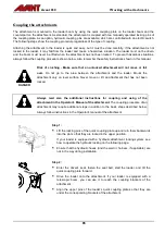
Page 86: ...pins are in the lower position and come through the fasteners on the attachment on both sides Hydraulic attachment coupling The optional hydraulic attachment coupling plate enables locking and unlock...

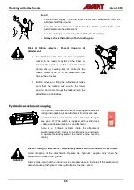
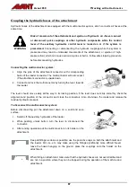
Page 87: ...connector is upside down 2 Connect and lock the multiconnector by turning the lever towards the loader The lever should move easily all the way to its locking position If the lever does not slide smoo...

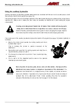
Page 88: ...of the auxiliary hydraulics and electric buttons of the joystick see page 50 directs hydraulic oil as follows 1 Moving the control lever towards the locking position will direct hydraulic flow to por...

Page 89: ...all movements have stopped Extra auxiliary hydraulics coupling The extra hydraulics coupling is a double acting hydraulic with two fittings A pair of standard type hydraulic quick couplings are locat...

Page 90: ...guides which can also be lubricated If a hydraulic attachment is mounted on the hydraulic side shift adapter the loader must be equipped with the optional second auxiliary hydraulics outlet in the fr...

Page 91: ...be used only on level ground CAUTION Adapter plates reduce lifting capacity Do not use adapters with heavy loads or attachments The adapter plates move the centre of gravity of the attachment further...

Page 92: ...ber to remove the frame lock and test the steering of the loader after transport Tie down points The loader must be tied down securely if transporting it on a trailer for example All four tie down poi...

Page 93: ...e center of gravity of a loader without an attachment is located slightly forward from the rear axle Take into account the size and weight of the attachment and any additional counterweights on the lo...

Page 94: ...18623 installed at the side of rear frame For side installation two brackets are needed Tie down bracket on wheel hub A423091 Installed to a wheel hub with 5 bolts DANGER Risk of moving or falling of...

Page 95: ...g term storage Inflate the tyres to the recommended tyre pressure Fill the fuel tank and the hydraulic oil tank to the maximum marks Cover the engine exhaust pipe outlet Lifting of the loader Lifting...

Page 96: ...s the principle of lifting a loader with the ROPS frame using four lifting straps WARNING Risk of dropping of loader Never attempt to lift the loader from the counterweights or use them as tie down po...

Page 97: ...ty instructions WARNING Always follow the basic safety procedures and keep the following instructions in mind when doing any maintenance or service 1 Switch off the loader and let it cool down before...

Page 98: ...ry might be barely visible but serious injury can develop within just hours WARNING Risk of injuries and burns caused by leaking hydraulic oil Never operate loader or attachments if there are hydrauli...

Page 99: ...ompletely before opening WARNING Risk of contact with moving parts Always shut down the engine before accessing the engine compartment Engine cooling fan alternator belt and belt pulleys will move at...

Page 100: ...anual nut 5 While seated on the driver s seat keep the engine off and lower the boom until it rests on the service support Service support is stored at the front storage compartment Service support in...

Page 101: ...operations are intended to be made when the loader engine is off except those checks that are specifically intended to be made with the engine running Follow the recommended service schedule Keep rec...

Page 102: ...clean Check that all controls of the loader function correctly Daily and weekly inspections Check before each work shift Check weekly 1 Add fuel 2 Check the general condition of the loader its equipme...

Page 103: ...harge pressure of the variable displacement pump 15 Measure the power control valve adjust if necessary 16 Check and adjust slide pads of telescopic boom replace if necessary 17 Check mounting and ope...

Page 104: ...injector failure Risk of fire or explosion Handle fuel with care DANGER Always stop the engine and allow it to cool before refuelling Refuel only in a well ventilated area Use only diesel fuel that is...

Page 105: ...outer appearance A dirty machine will run hotter and will collect more dirt into the air cleaner and radiators which may shorten the service life of the engine or hydraulic components Keep engine are...

Page 106: ...ling is essential To prevent overheating clean screens cooling fins and other external surfaces of engine Avoid spraying water at wiring harness or any electrical components The loader is equipped wit...

Page 107: ...sured Lack of lubrication will cause the joints to wear quickly Use general purpose machine grease A grease gun is needed to apply grease to grease nipples All lubrication nipples are standard R1 8 ni...

Page 108: ...g use The telescopic inner part of the boom must not move significantly when manually handling it If it is necessary to adjust or to replace the slide pads see page 121 Check the steering cylinder its...

Page 109: ...tandard metric system type If replacement of bolt or nut is necessary replace both at the same time with ones that are identical in size and grade Most bolts and nuts on the loader are metric grade 8...

Page 110: ...oupling plate Check the locking of attachment and locking pins on attachment coupling plate Check both locking pins Both pins must move easily and come through the lower brackets of the attachment To...

Page 111: ...ver overfill the hydraulic oil tank Oil can flow over or foam inside tank There is a breather filter inside the dipstick cap which must be cleaned or changed once a year 10 Check engine oil level Chec...

Page 112: ...rties of the coolant diminish over time 12 Check water separator Water in fuel can cause significant damage to the injection system of the engine Always use only clean fuel that is stored in container...

Page 113: ...r on the right side of the engine You can do the routine battery related checks by removing only the top panel of the rear frame engine cover To fully access the battery remove the rear right panel of...

Page 114: ...ainst other parts of the loader 3 Check cables for signs of aging and wear If a cable or its insulation has damaged worn or become brittle there is an increased risk of short circuit and fire 4 Check...

Page 115: ...ttachment only for its intended use 17 Check drive control and steering Check operation of pedals and steering Pedals must move freely and not get stuck or feel stiff Check that loader stops when not...

Page 116: ...sor 1 Add or remove the counterweights from the loader 2 Remove the engine cover plate and the lower left side rear cover plate 3 Lift something so heavy with the loader that the rear wheels lift off...

Page 117: ...new one Take used filter to recycling 4 Change hydraulic oil When changing hydraulic oil you can remove the oil with a suction pump or by opening the drain plug on the right side of the front frame n...

Page 118: ...ough a pre filter Both fuel filters are located on the left hand side of the engine near the fuel tank Replace fuel filters carefully to avoid fuel spill Make sure to keep all parts clean during servi...

Page 119: ...only with a correct type of battery Wrong type of battery can cause risks of fire explosion and release of battery acid The battery must meet the specifications of the original battery Part number 651...

Page 120: ...Never adjust pressure to higher level than recommended setting The electric drive system is designed to operate at the intended pressure level Other settings can damage electric drive modify the respo...

Page 121: ...aulic drive pump optimizes driving performance of the loader by reducing stalling of the loader when load increases quickly and by making starting and stopping of the loader smoother The valve is inst...

Page 122: ...r nearest Avant service partner Slide pad part numbers Slide pad 1 A430928 Adjustment sheet long A430931 Slide pad 2 A430929 Adjustment sheet short A430932 Slide pad 3 A48343 Slide pad 4 A47922 Spacer...

Page 123: ...ort and the frame lock are stored in their place and that they have the necessary locking parts Test the function of the reverse beeper if installed on the loader If the loader is equipped with a cab...

Page 124: ...3 Change cab air filter Change the cab air filter at least once a year If you operate the loader frequently in dusty conditions change the filter more often For example if you use the loader for seaso...

Page 125: ...ssible fuse box is located on the right side panel near drivers seat 12 V Fuse box 1 1 ECU Parking brake release 2 Dashboard Drive speed range selection switch 3 12 V oultet 4 ECU diagnostics ECU star...

Page 126: ...ted with auxiliary power if necessary by using appropriate strong enough jump start cables 1 Connect first one end of the positive cable to the positive post of the dead battery 2 Connect the other en...

Page 127: ...le can get severely damaged when giving or receiving auxiliary starting power Avant takes no responsibility of damages caused by giving or receiving auxiliary power CAUTION Risk of electric shock spar...

Page 128: ...Avant 850 128...

Page 129: ...filter clean fuel lines Cold ambient temperature Hold ignition key in glow position long enough If glow indicator lamp is lit allow it to turn off before starting Extend starting time up to 5 seconds...

Page 130: ...air if necessary Hydraulic oil flow restricted Make sure auxiliary hydraulics valve is completely opened when using high flow attachments Adjust lever locking plate if necessary Hydraulic system overl...

Page 131: ...g hours Remarks Serviced by Stamp signature ___ ___ _____ _____ 50 h ___ ___ _____ _____ 450 h ___ ___ _____ _____ 850 h ___ ___ _____ _____ 1250 h ___ ___ _____ _____ 1650 h ___ ___ _____ _____ 2050...

Page 132: ...Avant 850 132 Notes...

Page 133: ...Avant 850 133 Notes...

Page 134: ...m pivot pins and other metal structures visually 105 108 Check the general condition of the loader 105 Check the movements of boom 115 Check the safety frame seat seat belt lamps and other safety rela...

Page 135: ...gradients and near excavations 14 Operator qualification 6 Opticontrol option 53 129 OptiDrive 76 Overview of controls 46 P Parking brake switch 52 Periodic service 117 Personal safety and protective...

Page 136: ...auxiliary hydraulics 88 V Ventilation and heating 47 69 W Warning beacon option 47 67 Warning lights on CAB GT 67 Windscreen washer and wiper 69 Work lights 66 Working near powerlines 17 Working with...

Page 137: ...orie ENGINS DE TERRASSEMENT CHARGEURS CHARGEURS COMPACTS Kategorie ERDBEWEGUNGSGER T LADER KOMPAKTLADER Original language Langue d origine Originalsprache Original language version Model Mod le Modell...

Page 138: ...AVANT has a policy of continuous development and retains the right to change specifications without notice 2020 Avant Tecno Oy All rights reserved www avanttecno com...

Reviews:

Related manuals for Avant 850