background image

Introduction, warranty

3

300S Series

INTRODUCTION

AVA

NT TECNO OY

 wants to thank you for purchasing an 

AVA

NT

 loader. It is the result of Avant’s long

experience in design and manufacturing of compact loaders.

We ask you that you read and understand the contects of this manual completely before operating the loader.

This will improve your operating and maintenance efficiency, help avoid breakdowns and damage and extend

your machine’s life.

Contact your local 

AVA

NT

 dealer for any questions, service, spare parts or about any problems that may occur

with the operation of your machine.

AVA

NT

 300S SERIES WARRANTY

This warranty specifically applies to the 

AVA

NT 300S

 series loaders only and not to any attachments used

with this product.

Any repairs or modifications performed without the prior authorisation of 

AVA

NT


Tecno Oy

 will cancel this

warranty.

During the first two years of operation or the first 750 hours (whichever is the soonest) 

AVA

NT


Tecno Oy

warrants to replace any part or repair any defect which may occur, subject to the terms detailed below:

1) The product has received regular maintenance in accordance with schedules given by the manufacturer.

2) Any damage caused by operation in a negligent manner or exceeding the approved specifications detailed

in this manual is excluded.

3) 

AVA

NT


Tecno Oy

 accepts no responsibility for interruption to working or any other consequential losses

resulting from any failure of the product.

4) Only 

AVA

NT


Tecno Oy

 approved replacement or original quality parts shall be used during routine

maintenance.

5) Any damage caused by the use of incorrect fuel, lubricants, cooling liquid or cleaning solvents is exclude

6) The Avant Warranty excludes any consumable parts (e.g. tyres, spark plugs, batteries, filters, belts etc.)

except where it can be clearly shown that these parts were defective on original supply.

7) Any damage caused resulting from the use of attachments not approved for use with this product is excluded.

8) In the event a fault occurs which is attributable to manufacturing or assembly defect you should arrange

to return your AVANT to your authorised dealer for repair. Travel and freight costs are excluded.

IDENTIFICATION OF THE LOADER

Write down the following information about your loader, it will help you when ordering parts etc.

1. Model:  

AVA

NT

_____________________Purchase date:______________________________

2. Serial number:________________________________________________________________

3. Engine serial number:__________________________________________________________

The serial number and model of the loader are printed on the manufacturer’s plate which is located

in the footwell (decal no. 8, see page 6). Location of engine serial number can be found in the

operating manual of the engine.

Summary of Contents for 313S 2018

Page 1: ...313S 320S English Operator s Manual 2018 ...

Page 2: ...ICATION ENGINES 9 LOAD DIAGRAM 10 CONTROLS 11 STARTING THE ENGINE 14 STOPPING THE ENGINE 15 DRIVE CONTROL 15 DOUBLE SPEED FUNCTION 16 USING THE AUXILIARY HYDRAULICS 16 COUPLING THE ATTACHMENTS 17 300S SERIES SERVICE TABLE 18 SAFETY INSTRUCTIONS FOR MAINTENANCE 19 MAINTENANCE INSTRUCTIONS 20 REFUELING 21 FILTER LOCATION 22 FILTER TABLE 22 GREASING POINTS 300S SERIES 22 TROUBLESHOOTING 23 ATTACHMENT...

Page 3: ...ual is excluded 3 AVANT Tecno Oy accepts no responsibility for interruption to working or any other consequential losses resulting from any failure of the product 4 Only AVANT Tecno Oy approved replacement or original quality parts shall be used during routine maintenance 5 Any damage caused by the use of incorrect fuel lubricants cooling liquid or cleaning solvents is exclude 6 The Avant Warranty...

Page 4: ...MC and 2000 14 EC Noise Emission 5 Category EARTH MOVING MACHINERY LOADERS COMPACT 6 Model AVANT 7 Serial Number 8 Year of Manufacture 9 Directive Conformity Assessment Procedure Notified Body 2006 42 EC Self certification 2014 30 EC Self certification 2000 14 EC Type test 10 Name Risto Käkelä 11 Position Title Managing Director 12 Signature ___________________________ 13 Place Ylöjärvi Finland 14...

Page 5: ... gases or where exhaust can contact flammable material explosion or fire can result Do not transport the load with the boom lifted Always carry bucket or attachment as low as possible and put the load down whenever you leave the machine When lifting or lowering the load do not operate the boom control lever abruptly Turn the lever smoothly and with care Do not exceed rated operating capacity follo...

Page 6: ... Series l jk m n o r p q DECAL LOCATIONS The following decals and signs should always be installed on the loader If any of these decals has been removed or is unreadable it should be replaced without delay l j k m n o p q r ...

Page 7: ... extends 500 mm hydraulically Attachment coupling plate Attachments are mounted on the attachment coupling plate Auxilary hydraulics outlet The hydraulic hoses of hydraulically operated attachments are mounted on this outlet with quick couplers The outlet is double acting it has two pressure lines and one return line It is also possible to install an auxiliary hydraulics outlet in the rear of the ...

Page 8: ...rive hydraulic four wheel drive Auxiliary hyraulics flow and pressure 28 l min single pump 22 5 22 5 l min double pump 175 bar 22 5 22 5 l min 200 bar 22 5 22 5 l min 220 bar Turning radius same as the length of the machine same as the length of the machine same as the length of the machine same as the length of the machine Lifting height with standard boom 2100 mm 2100 mm 2100 mm Lifting height w...

Page 9: ...electric Bore stroke 88 64 mm 67 68 mm Displacement 389 cm3 719 cm3 Max output 10 kW 13 hp 14 kW 20 hp Fuel petrol min 92 oct diesel Fuel tank capacity 6 5 l 18 l Engine oil capacity 1 1 l 3 8 l Engine oil type API SE API CC Viscosity SAE 10W 30 SAE 10W 30 Valve clearance suction 0 15 mm 0 145 0 185 mm Valve clearance exhaust 0 20 mm 0 145 0 185 mm Sound pressure level LPA 84 dB A 88 dB A Sound po...

Page 10: ...driver weighing 80 kg For the 320S and 320S models the max load is 460 kg If the load is still 25 cm in front of the attachment coupling plate and a rear weight of 30 kg is added the max load increases to 350 kg for the 313S petrol model For the 320S and 320S models the max load is 510 kg CAUTION In practice the safe working load is 70 of the diagram values Do not load the loader with heavier load...

Page 11: ...ses 4 Hour meter 5 Charge indicator 6 Oil pressure indicator 7 Thermometer 8 Ignition switch Positions Off On Glow Start 9 Signal horn 10 Auxiliary hydraulics control lever models 313S and 320S 11 Control lever for telescopic boom Optional extra 12 Auxiliary hydraulics control pedal models 313S and 320S 13 Double speed control pedal models 313S and 320S 14 Throttle pedal 15 Parking brake handle tu...

Page 12: ... wheels turn backward reverse drive right side wheels Push left to lift the boom Push right to lower the boom 3 Control lever of auxiliary hydraulics models 313S and 320S Push forward carefully to find out which way the hydraulic attachment is functioning Pull backward The attachment operates in opposite direction Lock position Continous flow for rotary broom backhoe etc Model 320S Control lever o...

Page 13: ...s the pedal down to engage double speed function 3 Auxiliary hydraulics pedal Controls the auxiliary hydraulics function By pressing this pedal down the attachment operates in one direction by lifting the pedal upward the attachment operates in reversed direction ATTENTION Auxiliary hydraulics can also be operated with the control lever on the dashboard see previous page CONTROLS IN THE FOOTWELL 1...

Page 14: ... the ignition key to the right until engine starts then let the key return to ON position Reduce choke move choke lever to the right as soon as engine has started move completely to the right when engine has warmed up Diesel engine Avant 320S and 320S Turn the battery disconnect switch to ON Turn the ignition key to the right keep the ignition key in this position for approx 10 seconds depending o...

Page 15: ...abrubtly the movements will be jerky Drive speed can be increased with the throttle pedal The machine will stop as soon as one allows the levers to return to center neutral position Reverse driving Reverse driving happens exactly the same way as driving forward except that the drive control levers are now being pulled backwards Drive speed can be increased with the throttle pedal The machine will ...

Page 16: ... the left in the footwell see pages 12 and 13 The lever can be locked in the up right position in case continuous oil flow for the attachment is required e g with backhoe rotary broom etc On model 320S auxiliary hydraulics are controlled with the lever no 2 in the footwell left see page 13 When pulling the auxiliary hydraulics control lever upwards it locks into the locking position This facilitat...

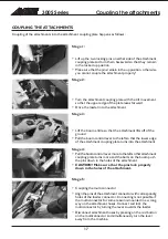
Page 17: ... Pull the boom control lever to the left so that the lower edge of the attachment coupling plate turns into the attachment Stage 4 Pull the boom control lever more to the left so that attachment coupling plate turns more and the bolts on the boom push the pins down in the holes of the attachment CAUTION Make sure that the pins lock properly down in the holes of the attachment Stage 5 Coupling the ...

Page 18: ...rrester 16 Change spark plug 17 Change air cleaner element 18 Check and adjust valve clearances DIESEL ENGINE 19 Check engine oil level 20 Change engine oil 21 Clean air filter 22 Clean fuel filter and sediment cup 23 Check condition and tightness of alternator belt 24 Check water hoses and hose clamps 25 Change engine oil filter 26 Change fuel filter 27 Clean fuel tank 28 Clean radiator cells 29 ...

Page 19: ...NING USE THE SERVICE SUPPORT ON THE BOOM CYLINDER DO NOT GO UNDER UNDSUPPORTED BOOM DO NOT SMOKE DURING SERVICE OPERATIONS BEWARE POSSIBLE HIGH PRESSURE IN HYDRAULIC CIRCUITS MOUNTING OF THE SERVICE SUPPORT SAFETY INSTRUCTIONS WHEN HANDLING THE BATTERY BATTERY CONTAINS CORROSIVE SULFURIC ACID AVOID CONTACT WITH SKIN OR CLOTHES IF ELECTROLYTE GETS ON YOUR SKIN OR CLOTHES FLUSH WITH A LOT OF WATER I...

Page 20: ...dipstick Refill when necessary Clean the area before checking hydraulic oil level Do not let any contaminents enter the hydraulic oil tank during this procedure 5 CHANGING OF HYDRAULIC OIL FILTER The hydraulic oil return filter is located on top of the hydraulic oil tank under the cover Take off the cover and replace the oil filter cartridge Remember to use the service support 6 HYDRAULIC OIL CHAN...

Page 21: ...mportant in order to avoid wear Most of the greasing points are on the loader boom There are 8 grease nipples altogether on a machine with standard boom and 14 grease nipples on a machine with telescopic boom The picture on page 22 shows the location of grease nipples 11 18 SERVICE PETROL ENGINE AVANT 313S is equipped with the Honda GX390 petrol engine Service and maintenance instructions for this...

Page 22: ...eturn 3 1 Lift cylinder upper end 2 Tilt cylinder both ends 3 Shot bolts on attachment coupling plate 4 Pivot pins on loader boom 5 Telescopic cylinder both ends 6 Telescopic boom FILTERS Following pictures and tables show the location and part numbers for the filters ATTENTION On older 300S series loaders with Kubota 14 hp or 20 hp diesel engine manufactured prior to 08 2002 the air filter may be...

Page 23: ..._________________________________________________________ 3 _________ __________ ________________________________________________________________ 4 _________ __________ ________________________________________________________________ 5 _________ __________ ________________________________________________________________ 6 _________ __________ _______________________________________________________...

Page 24: ... YLÖJÄRVI FINLAND Tel 358 3 347 8800 sales avanttecno com www avanttecno com AVANT has a policy of continuing improvement and retains the right to change specifications without notice 2018 AVANT Tecno Oy Kaikki oikeudet pidätetään 0318 ...

Reviews: