2
3
8
9
10
11
17
16
18
6
7
12
13
14
1
19
Operating instructions
16
525 LPG
2
1
3
4
15
Dashboard
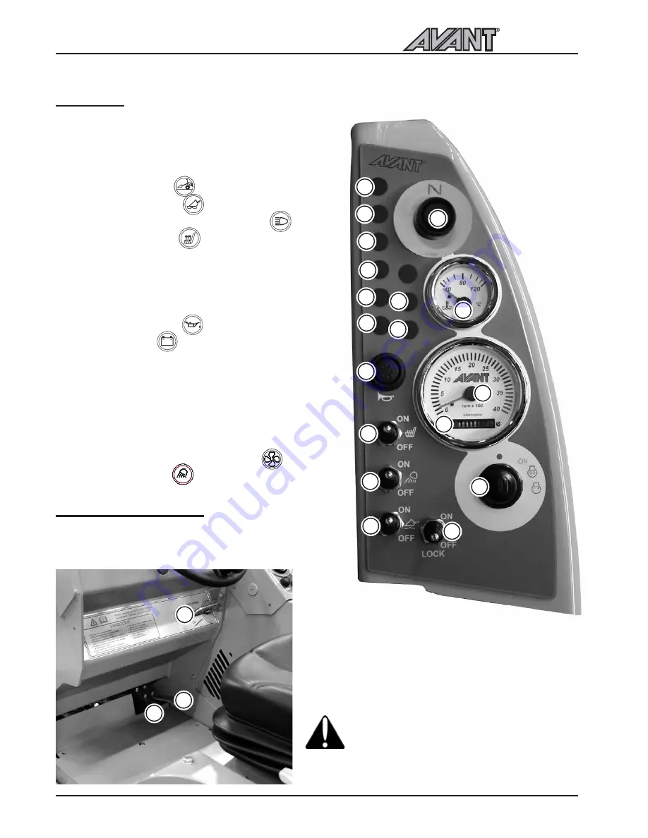
On the dashoard on the right side of the drivers seat
are mounted gauges, indicators and switches which
help the operator to control the loader.
Dashboard may be slightly different in different models.
Following picture shows the different functions:
1. Load sensor indicator
2. Boom floating indicator
3. Headlamp indicator (Road traffic light kit)
4. Seat heater indicator
6. Fuel gauge
7. Work light switch
8. Tachometer
9. Hour meter
10. Oil pressure indicator
11. Charge indicator
12. Thermometer
13. Ignition switch
14. Signal horn
15. Seat heater switch
16. Drive release / anti slip valve switch (optional extra)
17. Boom floating switch (optional extra)
18. Hydraulic cooler blower fuse indicator
19. Worklight indicator
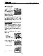
1. Drive pedal, left:
drive backward
2. Drive pedal, right:
drive forward
3. Parking/emergency brake handle
locking: pull the handle and turn down into locking
position
releasing: turn up and let the handle go down
Parking brake locks mechanically - spring-
loaded pins go into the holes of the parking
brake drum on the front wheels. Make sure
that the brake locks properly by driving a bit
forward or backward.
See correct operation of drive pedals on page 20.
Controls in the footwell
Following picture shows the controls located in the
footwell


