background image

5(18)

4.


Safety instructions for installing hydraulic components

The  following  safety  procedures  must  be  followed  when  handling  hydraulic  components.  Contact  your
nearest Avant dealer or service point if you have any additional questions or if you need installation services.
It is recommended to leave the installation of hydraulic components to professional service technicians.

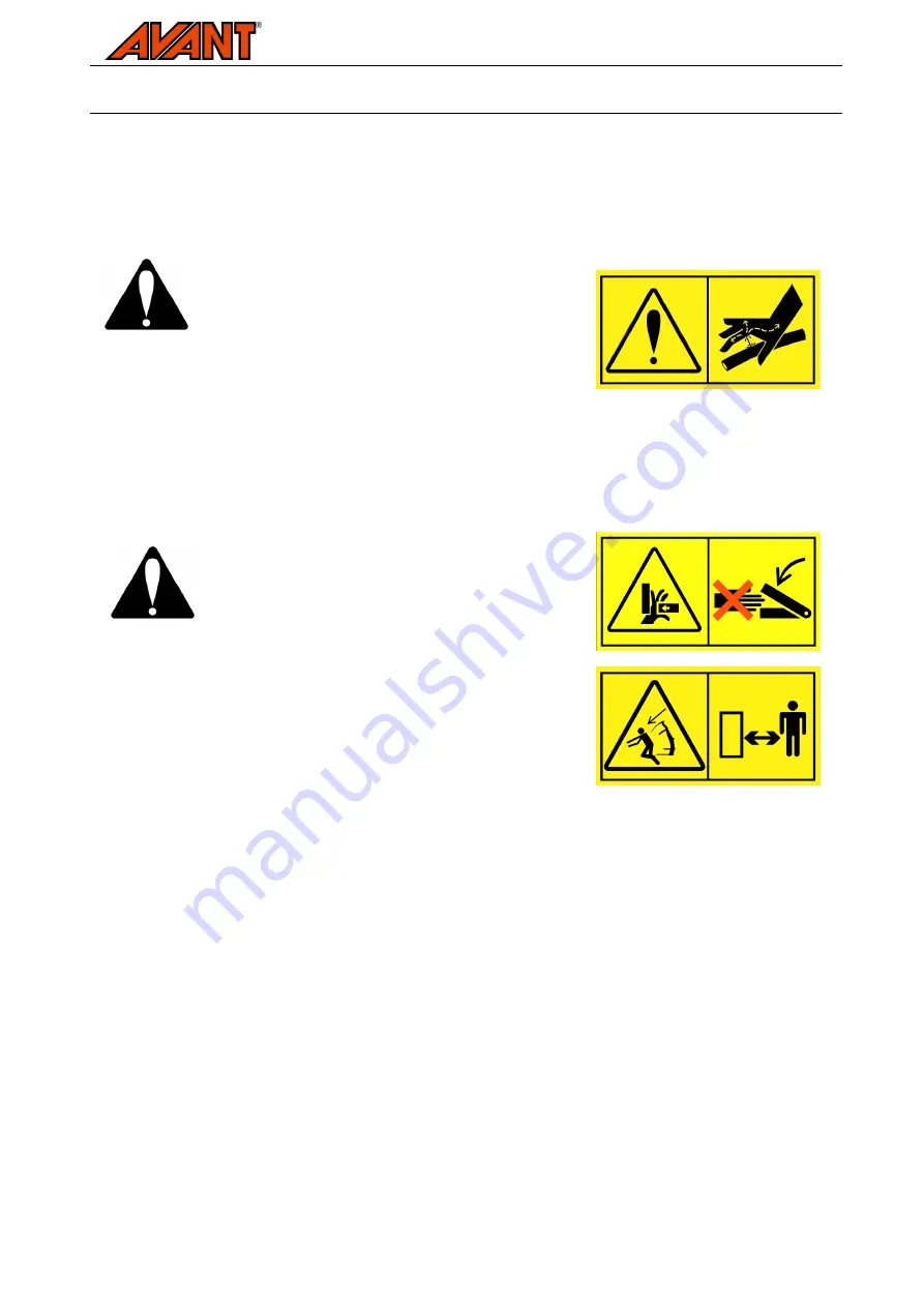
Before  handling  hydraulic  components,  make  sure

that the hydraulic system of the attachment and  the

loader  are  completely  depressurized.  Never  handle

pressurized  fittings.  See  instructions  on  page  14  to

release  the  residual  pressure.  Do  not  hold  your

hand  near  a  fitting  when  tightening  or  opening  it.

High pressure fluid ejection may penetrate skin  and

cause  serious  injuries.  Seek  medical  attention

immediately  in  case  hydraulic  fluid  is  injected  into

the skin.

Make  sure  the  attachment  is  securely  lowered  on

the ground. Any part of the attachment must  not  be

supported  only  by  the  hydraulic  pressure  or

hydraulic cylinders. Do not loosen any fitting as long

as  any  part  of  the  attachment  may  move.  Use

additional  supports  as  necessary.  Lower  the

attachment  securely  on  the  ground,  shut  down  the

loader  engine  and  lower  the  grapple  on  ground  or

additional  supports.  Depressurize  the  hydraulic

systems completely.

Ensure that the loader boom or any part of the attachment will not move and cause a crushing hazard:

1.  Lower the boom to its lowest position
2.  Lower the attachment firmly on the ground
3.  Lower  the  grapple  or  otherwise  block  the  movements  of  the  grapple.  Use  additional  supports  or

lifting equipment as needed.

4.  Shut down the loader engine.
5.  Move the auxiliary hydraulics control lever to its extreme positions several times to release residual

pressure.

Summary of Contents for A2868

Page 1: ... all instructions Keep this manual for later reference Operator s Operator s Operator s Operator s manual for Attachment manual for Attachment manual for Attachment manual for Attachment Silage forks Product number 300 700 series loaders A2868 A31512 A31519 Feeding table cleaning blade A2936 ...

Page 2: ...account to reduce the risk of personal injury or damage to property This safety symbol refers to important safety information in this manual It warns of an immediate hazard that could cause serious personal injury or damage to property Read the warning text accompanying the symbol carefully and ensure that other operators are also familiar with the warnings since personal safety is at stake This n...

Page 3: ...o available The rubber edge of the cleaning blade makes clearing of feeding tables easy before distributing fresh silage The cleaning blade can be attached without leaving the driver s seat If the hydraulic components are not preassembled the separately delivered installation kit must be installed before the attachment can be used Some previous experience about hydraulic handling hydraulic compone...

Page 4: ...accidental movement during storage Shut down the loader engine before any cleaning maintenance or adjustments Ensure that the equipment and the grapple are supported properly supported when going near the attachment Never go under a raised attachment or the loader boom Beware of the grapple which may be lowered even if the loader engine has been shut down Do not use the silage forks as an access p...

Page 5: ...tention immediately in case hydraulic fluid is injected into the skin Make sure the attachment is securely lowered on the ground Any part of the attachment must not be supported only by the hydraulic pressure or hydraulic cylinders Do not loosen any fitting as long as any part of the attachment may move Use additional supports as necessary Lower the attachment securely on the ground shut down the ...

Page 6: ...Do not go under a raised attachment or the loader boom keep a safe distance to lifted equipment A46803 Crushing hazard keep clear of moving parts Table 2 Silage forks technical data Product number A2868 A31512 A31519 Working width 800 mm 900 mm 1 050 mm Weight 85 kg 100 kg 120 kg Feeding table cleaning blade optional extra A2936 Spare part number for the lower tines 63990 63990 5 pcs A44511 2 pcs ...

Page 7: ...d boom For this reason the attachment must under no circumstances be lifted or moved when it has not been locked To prevent hazardous situations always follow the instructions provided in the following pages Also remember the safety instructions in Chapter 3 These instructions are applicable to mounting the silage forks to the boom quick attach plate of AVANT loaders that have standard quick attac...

Page 8: ...r lifting the attachment ensure that the locking pins are in the lower position and come through the fasteners on both sides Unlocked attachment may fall on the boom or operator and cause injuries Do not use the automatic locking of the locking pins at a height of over one metre If the locking pins do not return to the normal position when the front plate is tilted do not raise the attachment any ...

Page 9: ...instructions carefully To prevent unintentional movements of the grapple and oil spray do not connect the quick couplings or the multiconnector to the loader before the hydraulic hoses and all fittings have been tightened Contents of installation kit A45866 for 300 700 series A45866 Hose kit Ref Part Qty Description Ref Part Qty Description 1 65251 1 Multiconnector 10 A32277 2 Hydraulic hose L 190...

Page 10: ...to the cylinder with hexagonal screw type fittings Slide a seal ring on both sides of the banjo fitting and tighten to position shown in figures Note the welding on the cylinder and make sure that the hose is not in contact with the welding 4 Install the hose clamp to the attachment but do not tighten the clamp 5 Install the hydraulic couplings Conventional type quick couplings Slide the protectiv...

Page 11: ... far as possible When noticing clear increase in needed force tighten fitting by turning 1 3 to 1 2 turns using tools The fitting is not tightened by torque and it will not need a lot of force at any point when tightening Overtightening will break the fitting Try to twist the hydraulic hose by hands after tightening the fitting should stay firm Test to find any leaks Clean the hydraulic components...

Page 12: ...tem is pressurized Connecting or disconnecting the hydraulic couplings while the system is pressurized may lead to unintended movements of the attachment or ejection of high pressure fluid which can cause serious injuries Keep the fittings as clean as possible use the protective caps for the quick couplings on both the attachment and the loader Dirt ice etc may make using the fittings significantl...

Page 13: ...essure must be released To release the residual pressure shut down the engine and turn the auxiliary hydraulics control lever of the loader so many times so that the grapple is freely on the ground and it will no longer move If one of the hydraulic fittings will not connect due to the residual pressure in the system try to lift the grapple a little at the same time as the fitting is connected 7 Op...

Page 14: ...d be operated with the 1 pump setting of the auxiliary hydraulics when applicable When moving material with the forks ensure that the load will not fall towards driver s position 7 2 Feeding table cleaning blade optional extra With the help of the feeding table cleaning blade clearing the cattle feeding table can be done without demounting the silage forks from the loader The cleaning blade is att...

Page 15: ...iately after detecting them a small leak can quickly grow into a big one Do not use the equipment if you have discovered a fault in the hydraulic system Leaking hydraulic fluid may penetrate the skin and cause serious injuries Hydraulic fluid is also harmful to the environment Check hoses visually for cracks or abrasions Monitor the wearing of the hoses and stop the use if the surface layer of the...

Page 16: ... Replace any damaged nipples Lubricant must be added approximately every 10 operating hours Clean the end of the nipple before greasing Only add the grease amount of a couple of grease press pushes at a time 9 Warranty terms Avant Tecno Oy grants a warranty of one year 12 months for the attachment from the date of purchase The warranty covers repair costs as follows Work costs are covered if the r...

Page 17: ...visions of the Machinery Directive directive 2006 42 EC as amended The following harmonized standards have been applied SFS EN ISO 12100 SFS EN 982 ISO 4254 1 Wir erklären hiermit dass die nachstehend aufgeführte Maschine konform ist mit den Bestimmungen der EG Maschinenrichtlinie EG Richtlinie 2006 42 EG mit Änderungen Die folgende harmonisierte Normen wurden angewandt SFS EN ISO 12100 SFS EN 982...

Page 18: ......

Reviews: