background image

11(16)

With  the  left  control  lever  the  front  boom  of  the  backhoe  and  the  slewing  are  controlled.  The  right  lever
controls the main boom and the bucket of the backhoe.

Digging with the backhoe is the most efficient when the edge of the bucket is kept at an angle that allows the
edge to cut the soil the most effectively. Pull the edge of the bucket towards the loader with the left lever and
tilt  the  bucket  by  operating the  right  control lever  at the  same time. The  bucket  should  not  be  pressed  too
hard  downwards,  since  this  would  result  in  lifting  the  front  tires  of  the  loader,  and  digging  becomes
ineffective.

Beware of the caving in hazard in the excavation or near it. Do not drive near the edge

of the hole or allow children to play near it.

At the first  use  the movements  of the  backhoe may  be  imprecise  as  there might  be  air  trapped  in  the
hydraulic  components.  The  hydraulic  system  will  bleed  itself,  when  moving  all the  movements  to  their
extreme positions one by one.

6.2.


Adjusting the speed of the backhoe movements

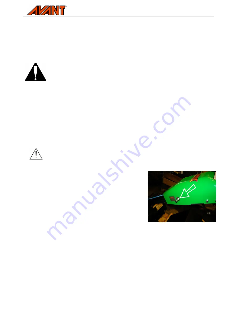
The  speed  of  the  backhoe  movements  can  be  adjusted  with  the  flow  divider  valve,  the  adjusting  screw  of
which  is  visible  at  the  left  side  of  the  control  valve  cover.  When  learning  to  use  the  backhoe  the  actual
working speed can actually be greater due to increased accuracy, even if the movements of the backhoe are
slower.

Note that adjusting the speed of the movements affects only the speed, not the force of
the backhoe.

The speed of backhoe movements can be adjusted as follows:

1.  Shut  down  the  loader  and  release  the  residual  pressure  as

described in section 5.2.

2.  Open the cap of the adjusting screw with a 14 mm spanner
3.  Loosen the locking screw of the adjusting screw with a 14 mm

spanner

4.  Turn the adjusting screw with an Allen key desired direction.
5.  When  a  suitable  setting  has  been  made,  tighten  the  locking

screw and fit the cap.

6.3.


Changing the bucket

The  bucket  of  the  backhoe  170  is  mounted  with  two  pivot  pins.  Change  the  bucket  when  the  backhoe  is
mounted  to  the  loader  and  use  the  service  support  described  in  section  7.1.  Place  the  bucket  near  the
ground. Remove the cotter pins and support the bucket while removing it. Use a soft hammer or a block of
wood to soften the hits, so that the pins will not get damaged. Do not hit directly at the pins. In most cases it
is  easier  to  remove the front  pin first.  When  mounting  the  new  bucket  remember  to  lock  the  cotter  pins  in
place.

Summary of Contents for A33748

Page 1: ...the equipment and follow all instructions Keep this manual for later reference Operator s Operator s Operator s Operator s manual for Attachment manual for Attachment manual for Attachment manual for Attachment Backhoe 170 Product number 300 700 series loaders A33748 ...

Page 2: ...sk of personal injury or damage to property This safety symbol refers to important safety information in this manual It warns of an immediate hazard that could cause serious personal injury or damage to property Read the warning text accompanying the symbol carefully and ensure that other operators are also familiar with the warnings since personal safety is at stake This notice symbol indicates i...

Page 3: ...er backhoe combination over The backhoe is not suitable for dredging The attachments have been designed to require as little maintenance as possible Regular maintenance tasks can be performed by the operator Not all maintenance tasks can be performed by the operator more demanding service or repairing tasks must be left to qualified professionals Appropriate protective equipment and original spare...

Page 4: ...not modify the structure of the attachment in a manner that would affect its safety Also read the safety instructions for the loader in the loader manual Note that both the boom of the loader and the backhoe move down even if the engine has been stopped Never go under a raised boom or the attachment Lower the backhoe on the ground before leaving the driver s seat Familiarise yourself with the load...

Page 5: ...ched completely New labels are available via your retailer or contact information provided on the cover page The warning decals contain important safety information Replace damaged or missing decals with new ones A46771 Read the instructions before use A46772 Do not go under a raised attachment keep a safe distance from raised or freestanding equipment A46803 Crushing hazard keep clear of moving p...

Page 6: ...rol valve boom of the backhoe Do not unfasten the valve boom strap until the backhoe is completely mounted to the loader 5 1 Mounting the backhoe to the loader The attachment is mounted to the loader boom by using the quick attach plate and the counterpart on the attachment In addition to this a locking bracket must be also installed Never move or raise an attachment that has not been locked The b...

Page 7: ...s The hydraulic couplers of the backhoe should connected so that the male coupling is connected to the coupling marked with a coloured cap on the loader The other hose is connected to the tank line free return line Before connecting or disconnecting hydraulic couplings shut down the loader engine and move the auxiliary hydraulics pedal on the loader to its extreme positions a few times This way th...

Page 8: ... amount of oil will be released beware of the oil Tighten the fitting immediately after the procedure The backhoe may move when the pressure is released stay clear from the equipment Wear protective goggles and gloves and wrap the fitting with cloth when releasing pressure from the hoses to prevent oil spilling 5 3 The valve boom of the backhoe Under the valve boom there is a supporting bracket wh...

Page 9: ...er s seat only 6 1 Operation To operate the backhoe lock the auxiliary hydraulics control pedal of the loader on When operating with the backhoe moderate engine rpm is often enough Higher rpm will not increase the digging force but if the engine stalls use a little higher revolutions Keeping the engine rpm low according to operating conditions will save fuel Keep the auxiliary hydraulics turned of...

Page 10: ...e outrigger Use the cotter pin to lock the adjustment pin Adjust the outriggers so that the front tires of the loader will rise slightly of the ground when the loader boom is set to its lowest position This way the control levers will be easy to reach and the best stability can be achieved The outriggers are equipped with spikes which can be used to keep the backhoe better in place during digging ...

Page 11: ...adjusting screw of which is visible at the left side of the control valve cover When learning to use the backhoe the actual working speed can actually be greater due to increased accuracy even if the movements of the backhoe are slower Note that adjusting the speed of the movements affects only the speed not the force of the backhoe The speed of backhoe movements can be adjusted as follows 1 Shut ...

Page 12: ...rained professional if unsure how to safely perform the task Never tighten a hydraulic fitting under pressure since the fitting may break and the released oil may cause serious injuries Do not use the equipment if you have discovered a fault in the hydraulic system 7 1 Service support At the side of the backhoe lifting boom there is a red service support which is intended to lock the booms for tra...

Page 13: ... of purchase The warranty covers repair costs as follows Work costs are covered if the repair is not performed at the factory The factory replaces any defective components or consumables The factory may reimburse the price of components purchased by the customer in special cases that have been agreed in advance The warranty does not cover Normal maintenance work such as the replacement of blades o...

Page 14: ... products listed below are in conformity with the provisions of the Machinery Directive directive 2006 42 EC as amended The following harmonized standards have been applied SFS EN ISO 12100 1 SFS EN ISO 12100 2 SFS EN 982 SFS EN 474 4 Wir erklären hiermit dass die nachstehend aufgeführte Maschine konform ist mit den Bestimmungen der EG Maschinenrichtlinie EG Richtlinie 2006 42 EG mit Änderungen Di...

Page 15: ......

Page 16: ......

Reviews: