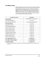


Level III Programming
31
Rev C
Level III Programming
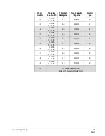
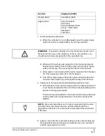
Historical information can be retrieved from the controller be pressing the
SET and DOWN buttons simultaneously, with the controller in the home
position. Release both buttons when the controller displays MODEL
NUMBER. Press the UP or DOWN buttons to navigate to each setting. The
readout will scroll across the top of the display and the value will be
displayed below the readout. Upon completing the initial programming
procedure the average daily usages will display the same value. These
values will changes as the unit logs water usage.
Scrolling Display Readout
Range/Values
MODEL NUMBER
a
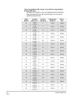
See Salt/Capacity Table on page 28
DAYS SINCE REGENERATION
0 to 255 days
PEAK FLOW RATE - DAY AND TIME
Language/Clock Mode Dependant
PEAK FLOW RATE GPM
a
0 to 47 GPM
WATER TREATED TODAY GAL
0 to 65536 gal.
WATER SINCE REGENERATION GAL
0 to 65536 gal.
SUNDAY AVERAGE USAGE GAL
0 to 65536 gal.
MONDAY AVERAGE USAGE GAL
0 to 65536 gal.
TUESDAY AVERAGE USAGE GAL
0 to 65536 gal.
WEDNESDAY AVERAGE USAGE GAL
0 to 65536 gal.
THURSDAY AVERAGE USAGE GAL
0 to 65536 gal.
FRIDAY AVERAGE USAGE GAL
0 to 65536 gal.
SATURDAY AVERAGE USAGE GAL
0 to 65536 gal.
TOTAL WATER USED GAL X 100
a
0 TO 999900 gal.
a
TOTAL WATER USED GAL X 1000000
a
0 to 42,940,000 gal.
a
MONTHS SINCE SERVICE
a
0 to 2184 months
a
a. Bold text indicates that specific values can be reset. Press and hold the SET button for 5 seconds to reset
the value.


