background image

38 

Troubleshooting

Rev C

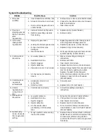
System Troubleshooting

Problem

Possible Cause

Solution

1. Brine tank 

overflow.

a. Uncontrolled brine refill flow rate.
b. Air leak in brine line to air check.

c. Drain control clogged with resin 

or other debris.

a. Remove brine control to clean ball and seat.
b. Check all connections in brine line for leaks. 

Refer to instructions.

c. Clean drain control.

2. Flowing or 

dripping water at 
drain or brine line 
after 
regeneration.

a. Valve stem return spring weak.
b. Debris is preventing valve disc 

from closing.

a. Replace spring. (Contact dealer.)
b. Remove debris.

3. Hard water 

leakage after 
regeneration.

a. Improper regeneration.

b. Leaking of external bypass valve.
c. O-ring around riser pipe 

damaged.

d. Incorrect capacity.

a. Repeat regeneration after making certain 

correct regenerant dosage was set.

b. Replace bypass valve. (Contact dealer.)
c. Replace O-ring. (Contact dealer.)

d. Verify appropriate regenerant amount and 

system capacity. (Contact dealer.)

4. Control will not 

draw brine.

a. Low water pressure.

b. Restricted drain line.
c. Injector plugged.
d. Injector defective.
e. Valve disc 2 and/or 3 not closed.

f. Air check valve prematurely 

closed.

a. Make correct setting according to 

instructions.

b. Remove restriction.
c. Clean injector and screen.
d. Replace injector and cap. (Contact dealer.)
e. Remove foreign matter from disc and check 

disc for closing by pushing in on stem. 
Replace if needed. (Contact dealer.)

f. Put control momentarily into brine refill. 

Replace or repair air check if needed. 
(Contact dealer.)

5. Control will not 

regenerate 
automatically.

a. AC adapter or motor not 

connected.

b. Defective motor.

a. Connect power.

b. Replace motor. (Contact dealer.)

6. Control 

regenerates at 
wrong time of 
day.

a. Controller set incorrectly.

a. Correct time setting according to 

instructions.

7. Valve will not 

draw brine.

a. Low water pressure.
b. Restricted drain line.
c. Injector plugged.
d. Injector defective.
e. Air check valve closes 

prematurely on brine pickup 
tube.

a. Set pump to maintain 20 psi at softener.
b. Change drain to remove restriction.
c. Clean injector and screen.
d. Replace injector. (Contact dealer.)
e. Put control momentarily into brine/slow 

rinse. Replace or repair air check if needed. 
(Contact dealer.)

8. System using 

more or less salt 
than regenerant 
setting.

a. Foreign matter in valve causing 

incorrect flow rates.

a. Remove brine control and flush out foreign 

matter. Advance control to brine/slow rinse,  
to clean valve (after so doing position 
control to "fast rinse” to remove regenerant 
from tank).

Summary of Contents for 269

Page 1: ...Models 269 Counter Current Conditioner Operations Manual...

Page 2: ...ain Line 12 Regenerant Line Connection 13 Overflow Line Connection 14 Electrical Connection 16 Valve Camshaft Green 17 Disinfection Of Water Conditioners 18 AvantaPure Controller 20 Display Icons 21 K...

Page 3: ...he AvantaPure controllers and Autotrol brand valves Knowledge of water conditioning and how to determine proper control settings Basic plumbing skills The directional instructions left and right are d...

Page 4: ...line should be done before connecting the drain line to the valve Excessive heat will cause interior damage to the valve Observe drain line requirements Do not use lead based solder for sweat solder...

Page 5: ...ine Refill Water is directed down through the resin bed to the regenerant tank at a controlled rate to create brine for the next regeneration 3 Brine Preparation The refill water is allowed to dissolv...

Page 6: ...6 System Operation Cycle Functions Rev C Cycle Water Flows BACKWASH SERVICE FAST RINSE REPRESSURIZE BRINE SLOW RINSE From Regenerant Tank To Regenerant Tank BRINE REFILL BRINE PREP...

Page 7: ...nstallation Valve Layout Refill Controller Regenerant Tube Connection Injector and cap Valve Discs Outlet Drain Inlet Backwash Injector Screen Camshaft Drain Control Filter Control Module Mount One Pi...

Page 8: ...re Controller LBS PM MIN KG x100 LCD Display Manual Regen Button Down Button Set Button Up Button For Future Use Turbine Input or Dry Contact Signal Input Main Motor Optical Sensor Connection AC Adapt...

Page 9: ...onditioning system is installed outdoors several items must be considered Moisture The valve and controller are rated for NEMA 3 locations Falling water should not affect performance The system is not...

Page 10: ...Water Line Connection A bypass valve system should be installed on all water conditioning systems Bypass valves isolate the conditioner from the water system and allow unconditioned water to be used...

Page 11: ...der WARNING Do not use tools to tighten plastic fittings Over time stress may break the connections When the 1265 bypass valve is used only hand tighten the nuts WARNING Do not use petroleum grease on...

Page 12: ...tional 10 psi 69 bar of water pressure at the drain connector 4 Where the drain line is elevated but empties into a drain below the level of the control valve form a 7 inch 18 cm loop at the far end o...

Page 13: ...ir leaks Even a small leak may cause the regenerant line to drain out and the conditioner will not draw regenerant from the tank This may also introduce air into the valve causing problems with valve...

Page 14: ...ne locate hole on side of tank Insert overflow fitting into tank and tighten with plastic thumb nut and gasket as shown Figure 5 Attach length of 1 2 inch 1 3 cm I D tubing not supplied to fitting and...

Page 15: ...Overflow Line Connection 15 Rev C Figure 6 Regenerant Tank Check Valve Furnished as an option from system manufacturer...

Page 16: ...ached to a flat surface Installations that do not provide easy access to the valve can have the controller mounted for remote operation A remote mount connection PN 1256257 is available for the Avanta...

Page 17: ...ycle is currently in progress Figure 7 Camshaft Front End for 269 Valve Bodies The corresponding slot for the number is positioned at the optical sensor which is approximately 90 degrees out of phase...

Page 18: ...e following methods Sodium or Calcium Hypochlorite Application These materials are satisfactory for use with polystyrene resins synthetic gel zeolite greensand and bentonites 5 25 Sodium Hypochlorite...

Page 19: ...used directly without dissolving before use 1 Dosage A Two grains approximately 0 1 ounce 3 mL per cubic foot 2 Regenerant tank conditioners A Backwash the conditioner and add the required amount of...

Page 20: ...ns Controller Memory Information entered or calculated by the controller is stored in two different ways A static memory will store Model number Regenerant setting Time of regeneration Days between re...

Page 21: ...ts 4 When LBS is displayed the value entered is in pounds 5 When Kg is displayed the value entered is in kilograms or kilograins 6 Four digits used to display the time or program value Also used for e...

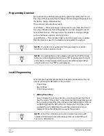
Page 22: ...troller is programmed using the buttons on the keypad The programming instructions will be described two ways whenever a section has keypad input First a table shows simplified instructions Second tex...

Page 23: ...t see the Level II Programming section The controller can be programmed to regenerate on specific days of the week See Level II Programming section If electrical power is not available the camshaft ca...

Page 24: ...They include Time of Day Day of Week Time of Regeneration Setting Time of Day Upon initial start up of the controller you will need to set the time of day The words Time of Day will scroll across the...

Page 25: ...is flashing Setting Regeneration Time The Regeneration Time is the setting which allows the programmer to select the time of day that regeneration should occur The words REGENERATION TIME will scroll...

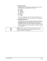
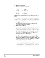
Page 26: ...o the selected default values Setting the Calendar Override Calendar Override allows the programmer to set the maximum days between regenerations A setting of 0 zero means the calendar override is dis...

Page 27: ...tting has been reached Setting the Language The controller is capable of displaying 6 different languages They are as follows 1 English 2 Spanish 3 French 4 Italian 5 Flemish 6 German Press the SET bu...

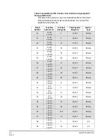
Page 28: ...Ft3 10 17 000 3 Bump 43 9 X 48 1 00 Ft3 2 5 10 000 4 Bump 44 9 X 48 1 00 Ft3 3 5 12 000 4 Bump 45 9 X 48 1 00 Ft3 8 5 20 000 4 Bump 46 9 X 48 1 00 Ft3 13 22 000 4 Bump 47 10 X 40 1 00 Ft3 2 5 10 000...

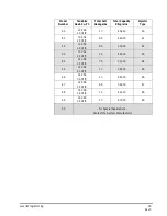
Page 29: ...63 64 14 X 65 3 00 Ft3 7 5 31 000 64 65 14 X 65 3 00 Ft3 11 39 000 65 66 14 X 65 3 00 Ft3 20 54 000 66 67 14 X 65 3 50 Ft3 8 5 36 000 67 68 14 X 65 3 50 Ft3 12 42 000 68 69 14 X 65 3 50 Ft3 20 57 000...

Page 30: ...ammed length of time has been reached the words CALL DEALER FOR SERVICE will appear in the banner display to signal the end user that regular maintenance may be required If it is set to 0 zero the fun...

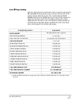
Page 31: ...ge Values MODEL NUMBERa See Salt Capacity Table on page 28 DAYS SINCE REGENERATION 0 to 255 days PEAK FLOW RATE DAY AND TIME Language Clock Mode Dependant PEAK FLOW RATE GPMa 0 to 47 GPM WATER TREATED...

Page 32: ...begin regeneration The display will show eight LEDs moving from left to right on the banner display indicating that the motor is running Additionally the display will show the total regeneration time...

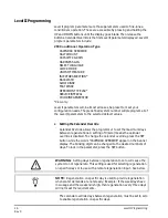
Page 33: ...k to cover the screen located at the end of the air check assembly at the bottom of the regenerant tank If the tank has a salt platform in the bottom of the tank add water until the water level is app...

Page 34: ...Draw Slow Rinse cycle 10 Draw water from the regenerant tank A With the controller in this position check to see that the water in the regenerant tank is being drawn out of the tank The water level i...

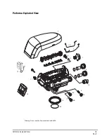
Page 35: ...Performa Exploded View 35 Rev C Performa Exploded View 2 1 3 4 5 6 7 8 9 10A 11 12 14 16 17 7 15 10B 11 Warning Do not use the flow control ball with 10A 13 18 20 19...

Page 36: ...Adapter Kit 9 Injector High Efficiency Options 1001611 3 4 inch BSPT Brass Pipe Adapter Kit 1032980 Injector Assembly 4 bumps 1001610 1 inch NPT Brass Pipe Adapter Kit 1032982 Injector Assembly 5 bump...

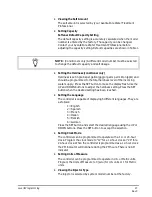
Page 37: ...onnected Verify that motor wire harness is connected to motor and controller module Verify that optical sensor is connected and in place Verify that motor gear has engaged cam gear If everything is co...

Page 38: ...d a Make correct setting according to instructions b Remove restriction c Clean injector and screen d Replace injector and cap Contact dealer e Remove foreign matter from disc and check disc for closi...

Page 39: ...lean water Turbine should spin freely If not replace meter Contact dealer 13 Run out of conditioned water between regenerations a Improper regeneration b Incorrect regenerant setting c Incorrect hardn...

Page 40: ...40 Troubleshooting Rev C...

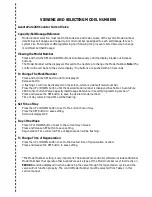
Page 41: ...model number is displayed See Table 1 AvantaPure 269 Counter Current Valve Capacity Salt Dosage Reference in Level II programming section Press and release the SET button to save the desired model nu...

Page 42: ......

Page 43: ...VIEWING AND SELECTING MODEL NUMBERS 43 Rev C...

Page 44: ...Copyright 2006 General Electric Company Printed in USA P N 3001122 Rev C...

Reviews: