- 11 -
INSTALLATION INSTRUCTIONS
Mount the Drive Rail as per Method A or B.
Mount the Control Box either next to the Drive Rail (via the Control Box mounting holes located within the
Control Box cover) utilizing the standard cable provided OR on a side wall of the garage (via the 3 hanging
mounts located on the base of the Control Box) using the optional cable extension kit.
Important Notes:
a.
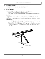
With the garage door in the fully open position the underside of the Drive Rail should be no
more than 50mm above the highest arcing point for its entire length. Mounting the Drive Rail
more than 50mm above the Highest Arcing Point of the garage door may cause the Drive Rail
to flex excessively. (Fig. 7)
b.
The ceiling structure must be adequate to support the weight of the AGDO. It is entirely up to
the installer to determine the structural suitability of the fixing points.
8.
Attaching Towing Arms
Close the garage door.
Remove the Drive Unit cover and insert the Straight Towing Arm through the slot in the cover (use the end
of the arm which has only one single hole)
Attach the arm to the Drive Unit using the short clevis pin and spring clip and then replace the cover.
Attach the Bent
Towing Arm to the Towing Bracket (use the end of the arm which has only one hole)
With the Drive Unit
disengaged
(Fig.10) position the Drive Unit in either one of the following ways;
i.
Adaptive mode ~ any distance from the end of the Drive Rail. (Fig.9)
ii.
Manual Mode ~ 225mm from the end of the rail to the front of the Drive Unit. (Fig.9)
Bring the Straight and Bent Towing Arms together and align the 2 furthest apart sets of holes.
Important Note: The 2 arms should be connected in a way that makes them as long as possible.
Securely fix the arms together using 2 x 8mm screws and nuts.
Fig. 6
Fig. 7
Fig. 8
Fig. 9
Summary of Contents for SDO-21 DP
Page 1: ...1...
Page 2: ...2...
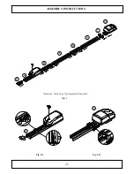
Page 8: ...8 ASSEMBLY INSTRUCTIONS Sectional Track Type Tip Up assembly depicted Fig 3 Fig 3A Fig 3B...
Page 28: ...28 NOTES...


