- 4 -
IMPORTANT SAFETY RECOMMENDATIONS
FAILURE TO COMPLY WITH THE FOLLOWING SAFETY RECOMMENDATIONS MAY
RESULT IN SERIOUS PERSONAL INJURY, DEATH AND / OR PROPERTY DAMAGE
.
1.
PLEASE READ CAREFULLY AND ADHERE TO ALL SAFETY AND INSTALLATION
RECOMMENDATIONS
2.
The installation of your new Automatic Garage Door Opener (herein after referred to as “AGDO”)
must be carried out by a technically qualified or licensed person. Attempting to install or repair the
AGDO without suitable technical qualification may result in severe personal injury, death and / or
property damage.
3.
The AGDO must only be installed on a properly balanced well functioning garage door. An improperly
balanced or malfunctioning garage door could cause serious personal injury, death and / or property damage.
Have a qualified person check and if required, make repairs to your garage door
before
installing the AGDO.
The garage door is deemed to be well balanced and aligned if it;
a.
requires an equivalent amount of applied force to either manually open or close, and
b.
requires no more than 150N (15kg) of applied force to either manually open or close, and
c.
does not rise or fall more than 100mm when released at any point between fully open or fully closed
positions, and
d.
does not rub on or incorrectly make contact with any supporting or surrounding structures, and
e.
the horizontal tracks have been installed level, and
f.
the door panels have been installed level, and
g.
the vertical tracks have been installed plum, and
h.
the junction between the curved horizontal track and the vertical track does not cause the door to “jump”
4.
The counter balance springs on sectional type garage doors
must
be properly lubricated between all of the
coils with heavy automotive bearing grease. Failure to adequately lubricate the springs may result in one or
more of the following symptoms:
a.
Counter balance springs may become rusty over time resulting in additional operating friction between
the coils which may cause the AGDO to malfunction.
b.
Seasonal temperature changes may cause the garage door springs to expand and / or contract. The
resultant increase and / or decrease in operating friction may cause the AGDO to malfunction. Properly
lubricating the springs will help to minimize changes in operating friction due to the effects of seasonal
temperature change.
5.
Remove or render inoperative all existing locks and ropes prior to installation of the AGDO.
6.
Repairs to the garage door must be carried out by technically qualified persons. Attempting to repair the
garage door without suitable technical qualification may result in severe personal injury, death and / or
property damage.
7.
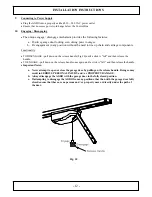
Where possible, install the AGDO at least 2 meters or more above the ground. Adjust the Engage / Disengage
Cord so that it hangs approximately 1.8 meters from the ground.
8.
The Header Bracket carries ALL of the opening and closing thrust of the AGDO and as such must be securely
fastened to a rigid, structural member of the garage wall or ceiling. It is entirely up to the installer to determine
the fixing method and the structural suitability of the fixing points.
9.
The ceiling structure must be adequate to support the weight of the GDO. It is entirely up to the installer to
determine the structural suitability of the fixing points.
10.
The Engage / Disengage Instruction Tag must remain attached to the Engage / Disengage Cord.
11.
Locate the Wall Switch;
a.
within site of the garage door, and
b.
at a minimum height of 1.5 meters above the ground so that it remains out of the reach of small children,
and
c.
away from all moving parts of the garage door
12.
The Entrapment Warning Label must be secured in a prominent position adjacent to the wall switch.
13.
The AGDO must be connected to a
properly earthed
general purpose 230 ~ 240VAC power outlet which has
been installed by a qualified electrical contractor.
14.
Do not connect the AGDO to the power outlet until this manual instructs you to do so..
Summary of Contents for SDO-21 DP
Page 1: ...1...
Page 2: ...2...
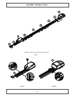
Page 8: ...8 ASSEMBLY INSTRUCTIONS Sectional Track Type Tip Up assembly depicted Fig 3 Fig 3A Fig 3B...
Page 28: ...28 NOTES...


