- 7 -
ASSEMBLY INSTRUCTIONS
3.
Assembly
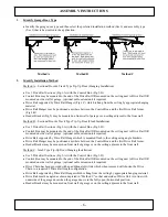
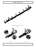
On a clean smooth surface open the packing carton and expose the AGDO components. (Fig.1)
Unfold the Drive Rail and Drive Chain Segments. (Fig.2-A)
Use the appropriate number of Drive Rails, Drive Rail Joiners and Chain Segments to suit the preferred
Installation Method, A, B or C. (Refer Sec.1 & 2)
Align and insert each Drive Rail Joiner (Fig.3-B) into a Drive Rail Segment (Fig.3-A) and push them
together until they are fully abutted and form one continuous Drive Rail Assembly.
Locate the Drive Rail Hanger (Fig.3-C) and insert the 2 gutter bolts provided. Slide the Drive Rail Hanger
onto the Drive Rail Assembly adjacent to the Control Box. (Fig.3-D) location.
Insert the Control Box into the Drive Rail Segment furthest from the garage door and then “Twist and Lock”
the Drive Chain (Fig.3B-D2) the Drive Chain into the Tensioning Block. (Fig.3B-D1).
Ensure that the plastic chain insulator ends are fully abutted and form one continuous piece.
Insert the Terminal Bracket (Fig.3-E) into the Drive Rail Segment closest to the garage door and then
“Twist and Lock” the Drive Chain (Fig.3A-E2) the Drive Chain into the Tensioning Block. (Fig.3A-E1)
Using a 12 mm socket wrench, tighten the Drive Chain Tensioner Bolt to the point where the underside of
the Bolt Head aligns with the Indicator Arrow on the Terminal Bracket. (Fig.3A-E3)
Fig. 1
Fig. 2
3.1
Options Selection
Refer to “Options and Features” on pages 17 ~ 26 and select the required Dip Switch functionality and
external accessory wiring as required.
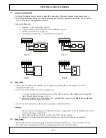
Dip Switches and external accessory wiring connections (Fig.16) can be accessed by removing the Control
Box Cover. (refer Sec.18 for removal and replacement details)
Once functionality selection and wire connection has been completed replace the Control Box Cover / Lamp
Bulb / Courtesy Lamp Cover and the AGDO is now fully assembled and ready for installation.
Summary of Contents for SDO-21 DP
Page 1: ...1...
Page 2: ...2...
Page 8: ...8 ASSEMBLY INSTRUCTIONS Sectional Track Type Tip Up assembly depicted Fig 3 Fig 3A Fig 3B...
Page 28: ...28 NOTES...


