


ASSEMBLY INSTRUCTIONS
8
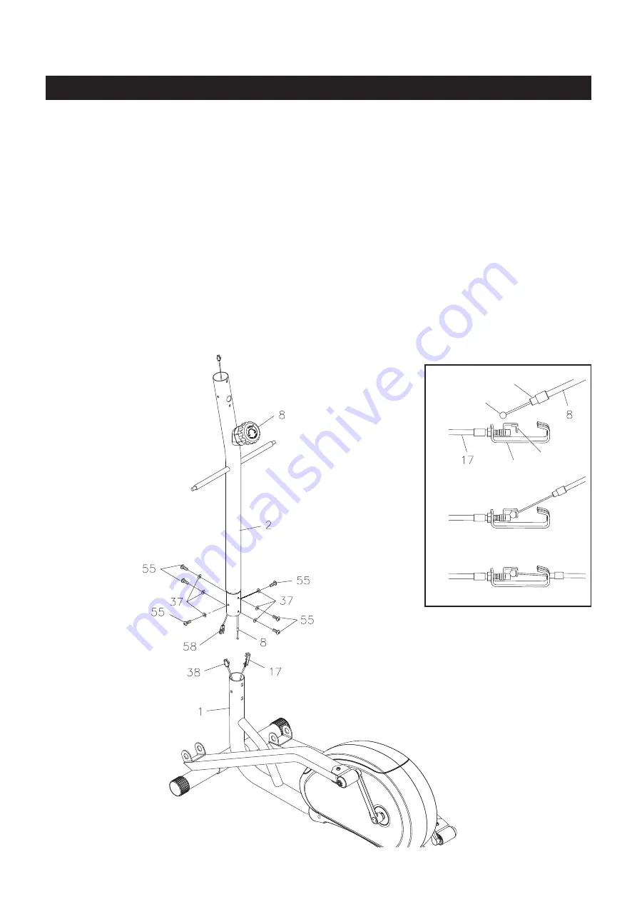
STEP 3
Refer to the inset drawing and the illustration below to connect the
TENSION KNOB(8)
to the
TENSION
CABLE(17)
and assemble the
UPRIGHT(2):
1. Set the
TENSION KNOB(8)
at position
“8”,
so the
CABLE END
extends out of the
METAL FITTING
as far as possible. Connect the
CABLE END
of the
TENSION KNOB(8)
to the
HOOK
on the end of the
TENSION CABLE(17).
2. Pull on the Cable of the
TENSION KNOB(8)
firmly
so that enough cable is available to allow the
METAL
FITTING
to go through the slot in the top of the
BRACKET.
3. Insert the
METAL FITTING
into the hole at the end of the slot in the
BRACKET.
4. Adjust the
TENSION KNOB(8)
and verify that the
HOOK
moves when the
TENSION KNOB(8)
is adjusted.
5. Connect the
EXTENSION WIRE(58)
to the
SENSOR WIRE(38).
6. Insert the
UPRIGHT(2)
into the
MAIN FRAME(1)
and secure with
BUTTON HEAD BOLTS(M8x1.25x25mm)
(55)
and
ARC WASHERS(M8)(37).
Cable End
Hook
Bracket
Metal Fitting
3
2
1
Summary of Contents for A550-090
Page 18: ...PRODUCT PARTS DRAWING BACK FRONT 18...
Page 22: ...NOTES 22...


