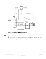
Figure 24: Traditional OPS application configuration
on page 136. Examples of such
applications are:
• a PBX in a central building serving stations in other buildings in the vicinity, such as in an
industrial park, often called a campus environment. Facilities can be provided by the local
exchange carrier or can be privately owned. Protection could be required.
• termination to other than a telephone, such as to a fax machine or a key telephone
system.
• individual circuits on the NT1R20 OPS analog line card can also be configured as On-
Premise Station (ONS) ports in LD 10:
- ONS service with hazardous and surge voltage protection (not available on other
analog line cards)
- to use otherwise idle NT1R20 OPS analog line card ports
Transmission considerations
The transmission performance of OPS lines depends on the following factors:
• the port-to-port loss for connections between OPS ports and other ports
• the transmission parameters of the facilities between the OPS port and the off-premise
station or termination
• the electrical and acoustic transmission characteristics of the termination
These factors must be considered when planning applications using the NT1R20 OPS analog
line card. They are important when considering configurations other than the traditional OPS
application as shown in
Figure 24: Traditional OPS application configuration
on page 136. The
following sections provide basic transmission planning guidelines for various OPS
applications.
Port-to-port loss
Loss is inserted between OPS analog line card ports and other ports in accordance with the
loss plan. This plan determines the port-to-port loss for each call.
When a port is configured for CLS OPS, loss is programmed into the OPS analog line card on
a call-by-call basis. When configured for CLS ONS, an OPS analog line card port is
programmed to a value that is fixed for all calls. The loss in the other port involved in the call
can vary on a call-by-call basis to achieve the total loss scheduled by the plan.
For satisfactory transmission performance, particularly on connections between the public
network and an OPS termination, it is recommended that facilities conform to the following:
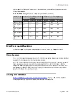
• Total 1 kHz loss from the local serving CO to the OPS terminal should not exceed 7.0 dB.
The total loss in the facility between the PBX and the terminal must not exceed 4.5 dB.
See
Figure 24: Traditional OPS application configuration
Application
Circuit Card Reference
July 2011 137
Summary of Contents for 1000 Series
Page 1: ...Circuit Card Reference Nortel Communication Server 1000 7 0 NN43001 311 04 04 July 2011 ...
Page 20: ...20 Circuit Card Reference July 2011 ...
Page 30: ...Introduction 30 Circuit Card Reference July 2011 Comments infodev avaya com ...
Page 116: ...Option settings 116 Circuit Card Reference July 2011 Comments infodev avaya com ...
Page 143: ...Figure 25 CP PIV card front Physical description Circuit Card Reference July 2011 143 ...
Page 148: ...NT4N39AA CP Pentium IV Card 148 Circuit Card Reference July 2011 Comments infodev avaya com ...
Page 287: ...Figure 86 Clock Controller Option 3 Operation Circuit Card Reference July 2011 287 ...
Page 302: ...NT5K21 XMFC MFE card 302 Circuit Card Reference July 2011 Comments infodev avaya com ...
Page 346: ...NT6D80 MSDL card 346 Circuit Card Reference July 2011 Comments infodev avaya com ...
Page 353: ...Figure 96 NTDK16 DLC Functional description Circuit Card Reference July 2011 353 ...
Page 461: ...Figure 147 Paging trunk operation Applications Circuit Card Reference July 2011 461 ...
Page 462: ...NT8D15 E and M Trunk card 462 Circuit Card Reference July 2011 Comments infodev avaya com ...
Page 500: ...NTAK09 1 5 Mb DTI PRI card 500 Circuit Card Reference July 2011 Comments infodev avaya com ...
Page 512: ...NTAK10 2 0 Mb DTI card 512 Circuit Card Reference July 2011 Comments infodev avaya com ...
Page 534: ...NTAK79 2 0 Mb PRI card 534 Circuit Card Reference July 2011 Comments infodev avaya com ...
Page 550: ...NTBK22 MISP card 550 Circuit Card Reference July 2011 Comments infodev avaya com ...
Page 560: ...NTBK50 2 0 Mb PRI card 560 Circuit Card Reference July 2011 Comments infodev avaya com ...
Page 595: ...Figure 165 MGC block diagram Introduction Circuit Card Reference July 2011 595 ...
Page 662: ...NTRB21 DTI PRI DCH TMDI card 662 Circuit Card Reference July 2011 Comments infodev avaya com ...
Page 668: ...NTVQ01xx Media Card 668 Circuit Card Reference July 2011 Comments infodev avaya com ...
Page 700: ......


