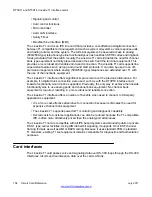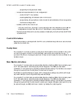
When the card is used to service off-premise terminal equipment through the public telephone
network, install a Channel Service Unit (CSU) as part of the terminal equipment to provide
external line protection.
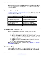
Environmental specifications
Table 70: Lineside T1 card - environmental specifications
on page 158 lists the environmental
specifications of the Lineside T1 card.
Table 70: Lineside T1 card - environmental specifications
Parameter
Specifications
Operating temperature-normal
15° to +30° C (+59° to 86°F), ambient
Operating temperature-short term
10° to +45° C (+50° to 113°F), ambient
Operating humidity-normal
20% to 55% RH (non-condensing)
Operating humidity-short term
20% to 80% RH (non-condensing)
Storage temperature
–50° to +70° C (–58° to 158°F), ambient
Storage humidity
5% to 95% RH (non-condensing)
Installation and configuration
Installation and configuration of the Lineside T1 card consists of six basic steps:
1. Configure the dip switches on the Lineside T1 card for the environment.
2. Install the Lineside T1 card into the selected card slots in the IPE shelf.
3. Cable from the I/O panel to the Customer Premise Equipment (CPE) or CSU, MMI
terminal or modem (optional), external alarm (optional), and other Lineside T1 cards
for daisy chaining use of MMI terminal (optional).
4. Configure the MMI terminal.
5. Configure the Lineside T1 card through the system software and verify self-test
results.
6. Verify initial T1 operation and configure MMI (optional).
Steps 1-5 are explained in this section. Step 6 is covered in
on page 175.
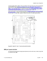
Dip switch settings
Begin the installation and configuration of the Lineside T1 card by selecting the proper dip
switch settings for the environment. The Lineside T1 card contains two dip switches, each
NT5D11 and NT5D14 Lineside T1 Interface cards
158 Circuit Card Reference
July 2011
Summary of Contents for 1000 Series
Page 1: ...Circuit Card Reference Nortel Communication Server 1000 7 0 NN43001 311 04 04 July 2011 ...
Page 20: ...20 Circuit Card Reference July 2011 ...
Page 30: ...Introduction 30 Circuit Card Reference July 2011 Comments infodev avaya com ...
Page 116: ...Option settings 116 Circuit Card Reference July 2011 Comments infodev avaya com ...
Page 143: ...Figure 25 CP PIV card front Physical description Circuit Card Reference July 2011 143 ...
Page 148: ...NT4N39AA CP Pentium IV Card 148 Circuit Card Reference July 2011 Comments infodev avaya com ...
Page 287: ...Figure 86 Clock Controller Option 3 Operation Circuit Card Reference July 2011 287 ...
Page 302: ...NT5K21 XMFC MFE card 302 Circuit Card Reference July 2011 Comments infodev avaya com ...
Page 346: ...NT6D80 MSDL card 346 Circuit Card Reference July 2011 Comments infodev avaya com ...
Page 353: ...Figure 96 NTDK16 DLC Functional description Circuit Card Reference July 2011 353 ...
Page 461: ...Figure 147 Paging trunk operation Applications Circuit Card Reference July 2011 461 ...
Page 462: ...NT8D15 E and M Trunk card 462 Circuit Card Reference July 2011 Comments infodev avaya com ...
Page 500: ...NTAK09 1 5 Mb DTI PRI card 500 Circuit Card Reference July 2011 Comments infodev avaya com ...
Page 512: ...NTAK10 2 0 Mb DTI card 512 Circuit Card Reference July 2011 Comments infodev avaya com ...
Page 534: ...NTAK79 2 0 Mb PRI card 534 Circuit Card Reference July 2011 Comments infodev avaya com ...
Page 550: ...NTBK22 MISP card 550 Circuit Card Reference July 2011 Comments infodev avaya com ...
Page 560: ...NTBK50 2 0 Mb PRI card 560 Circuit Card Reference July 2011 Comments infodev avaya com ...
Page 595: ...Figure 165 MGC block diagram Introduction Circuit Card Reference July 2011 595 ...
Page 662: ...NTRB21 DTI PRI DCH TMDI card 662 Circuit Card Reference July 2011 Comments infodev avaya com ...
Page 668: ...NTVQ01xx Media Card 668 Circuit Card Reference July 2011 Comments infodev avaya com ...
Page 700: ......


