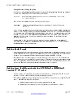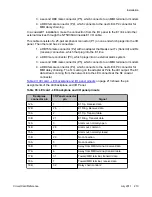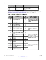
with the external alarm connections, MMI connections are optional. Up to 128 LEIs can be
linked, located in up to 16 separate IPE shelves, to one MMI terminal using the daisy chain
approach.
If only one LEI is installed, cable from the DB9 male connector labeled "P5" (toward MMI
terminal) to one of the COM ports on the back of any TTY, a PC running a terminal emulation
program, or a modem. For installations of only one card, no connection is made to the DB9
female connector labeled "P4" (away from MMI terminal).
If two or more LEIs are being installed into the system, the MMI port connections can be daisy-
chained together so that only one MMI terminal is required for up to 128 LEIs. See
LEI card - connecting two or more cards to the MMI
on page 217. Cards can be located in up
to 15 separate IPE shelves. Start with any card slot in the IPE shelf and connect to any other
card slot. Connected card slots do not need to be consecutive.
Connecting two or more LEIs to the MMI terminal
Follow this procedure for connecting two or more LEIs to the MMI terminal:
1. Cable the DB9 male connector labeled "P5" (toward MMI terminal) to one of the
COM ports on the back of any TTY, a PC running a terminal emulation program, or
a modem.
2. Make the connection from the first card to the second card by plugging the DB9
female connector labeled "P4" (away from MMI terminal) from the first card into the
DB9 male connector of the second card labeled "P5" (toward MMI terminal).
3. Repeat step 2 for the remaining cards.
4. At the last card of the daisy chain, make no connection from the DB9 female
connector labeled "P4" (away from MMI terminal).
5. If two LEIs are too far apart to connect the "P4" and "P5" connectors connect them
with an off-the-shelf DB9 female to DB9 male straight-through extension cable,
available at any PC supply store.
NT5D33 and NT5D34 Lineside E1 Interface cards
216 Circuit Card Reference
July 2011
Summary of Contents for 1000 Series
Page 1: ...Circuit Card Reference Nortel Communication Server 1000 7 0 NN43001 311 04 04 July 2011 ...
Page 20: ...20 Circuit Card Reference July 2011 ...
Page 30: ...Introduction 30 Circuit Card Reference July 2011 Comments infodev avaya com ...
Page 116: ...Option settings 116 Circuit Card Reference July 2011 Comments infodev avaya com ...
Page 143: ...Figure 25 CP PIV card front Physical description Circuit Card Reference July 2011 143 ...
Page 148: ...NT4N39AA CP Pentium IV Card 148 Circuit Card Reference July 2011 Comments infodev avaya com ...
Page 287: ...Figure 86 Clock Controller Option 3 Operation Circuit Card Reference July 2011 287 ...
Page 302: ...NT5K21 XMFC MFE card 302 Circuit Card Reference July 2011 Comments infodev avaya com ...
Page 346: ...NT6D80 MSDL card 346 Circuit Card Reference July 2011 Comments infodev avaya com ...
Page 353: ...Figure 96 NTDK16 DLC Functional description Circuit Card Reference July 2011 353 ...
Page 461: ...Figure 147 Paging trunk operation Applications Circuit Card Reference July 2011 461 ...
Page 462: ...NT8D15 E and M Trunk card 462 Circuit Card Reference July 2011 Comments infodev avaya com ...
Page 500: ...NTAK09 1 5 Mb DTI PRI card 500 Circuit Card Reference July 2011 Comments infodev avaya com ...
Page 512: ...NTAK10 2 0 Mb DTI card 512 Circuit Card Reference July 2011 Comments infodev avaya com ...
Page 534: ...NTAK79 2 0 Mb PRI card 534 Circuit Card Reference July 2011 Comments infodev avaya com ...
Page 550: ...NTBK22 MISP card 550 Circuit Card Reference July 2011 Comments infodev avaya com ...
Page 560: ...NTBK50 2 0 Mb PRI card 560 Circuit Card Reference July 2011 Comments infodev avaya com ...
Page 595: ...Figure 165 MGC block diagram Introduction Circuit Card Reference July 2011 595 ...
Page 662: ...NTRB21 DTI PRI DCH TMDI card 662 Circuit Card Reference July 2011 Comments infodev avaya com ...
Page 668: ...NTVQ01xx Media Card 668 Circuit Card Reference July 2011 Comments infodev avaya com ...
Page 700: ......


