Memory
The MSDL card contains two megabytes of Random Access Memory (RAM) for storing
downloaded peripheral software that controls MSDL port operations. The MSDL card includes
the shared RAM that is used as a communication interface buffer between the CPU and the
MPU.
The MSDL Flash Erasable Programmable Read Only Memory (Flash EPROM) also includes
the peripheral software to protect it against a power failure or reset. MSDL can copy peripheral
software directly from the Flash EPROM after power up or reset instead of requesting that the
system CPU download it.
The MSDL card also contains Programmable Read Only Memory (PROM) for firmware that
includes the bootstrap code.
Serial interface
The MSDL card provides one monitor port and four programmable serial ports that can be
configured for the following various interfaces and combinations of interfaces:
• synchronous ports 0–3
• asynchronous port 0
• DCE or DTE equipment emulation mode
• RS-232 or RS-422 interface
Transmission mode – All four ports of the MSDL can be configured for synchronous data
transmission by software. Port 0 can be configured for asynchronous data transmission for
CRT, TTY, and printer applications only.
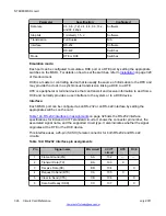
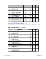
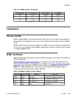
Equipment emulation mode – Configure an MSDL port to emulate DCE or DTE by setting
switches on the card and downloading LD 17 interface parameters.
I/O port electrical interface – Each MSDL port can be configured as an RS-232 or RS-422
interface by setting the switches on the MSDL card. MSDL ports use Small Computer Systems
Interface (SCSI) II 26-pin female connectors.
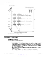
Figure 90: MSDL functional block diagram
on page 323 shows the system architecture using
the MSDL as an operational platform. It illustrates operation routing from the CPU, through the
MSDL, to the I/O equipment. It also shows an example in which DCH operation peripheral
software in the MSDL controls functions on ports 2 and 3.
Functional description
Circuit Card Reference
July 2011 321
Summary of Contents for 1000 Series
Page 1: ...Circuit Card Reference Nortel Communication Server 1000 7 0 NN43001 311 04 04 July 2011 ...
Page 20: ...20 Circuit Card Reference July 2011 ...
Page 30: ...Introduction 30 Circuit Card Reference July 2011 Comments infodev avaya com ...
Page 116: ...Option settings 116 Circuit Card Reference July 2011 Comments infodev avaya com ...
Page 143: ...Figure 25 CP PIV card front Physical description Circuit Card Reference July 2011 143 ...
Page 148: ...NT4N39AA CP Pentium IV Card 148 Circuit Card Reference July 2011 Comments infodev avaya com ...
Page 287: ...Figure 86 Clock Controller Option 3 Operation Circuit Card Reference July 2011 287 ...
Page 302: ...NT5K21 XMFC MFE card 302 Circuit Card Reference July 2011 Comments infodev avaya com ...
Page 346: ...NT6D80 MSDL card 346 Circuit Card Reference July 2011 Comments infodev avaya com ...
Page 353: ...Figure 96 NTDK16 DLC Functional description Circuit Card Reference July 2011 353 ...
Page 461: ...Figure 147 Paging trunk operation Applications Circuit Card Reference July 2011 461 ...
Page 462: ...NT8D15 E and M Trunk card 462 Circuit Card Reference July 2011 Comments infodev avaya com ...
Page 500: ...NTAK09 1 5 Mb DTI PRI card 500 Circuit Card Reference July 2011 Comments infodev avaya com ...
Page 512: ...NTAK10 2 0 Mb DTI card 512 Circuit Card Reference July 2011 Comments infodev avaya com ...
Page 534: ...NTAK79 2 0 Mb PRI card 534 Circuit Card Reference July 2011 Comments infodev avaya com ...
Page 550: ...NTBK22 MISP card 550 Circuit Card Reference July 2011 Comments infodev avaya com ...
Page 560: ...NTBK50 2 0 Mb PRI card 560 Circuit Card Reference July 2011 Comments infodev avaya com ...
Page 595: ...Figure 165 MGC block diagram Introduction Circuit Card Reference July 2011 595 ...
Page 662: ...NTRB21 DTI PRI DCH TMDI card 662 Circuit Card Reference July 2011 Comments infodev avaya com ...
Page 668: ...NTVQ01xx Media Card 668 Circuit Card Reference July 2011 Comments infodev avaya com ...
Page 700: ......


