of pins. Normally, these pin positions are cabled to 50-pin connectors at the I/O panel in the
rear of each module for connection with 25-pair cables to the MDF.
The information in
Table 160: NT8D02 Digital Line card - backplane pinouts
on page 359 is
provided as a reference and diagnostic aid at the backplane, because the cabling arrangement
can vary at the I/O panel. See Communication Server 1000M and Meridian 1 Large System
Installation and Configuration (NN43021-310) for cable pinout information for the I/O panel.
Table 160: NT8D02 Digital Line card - backplane pinouts
Backplane Pinout*
Lead Designations
Backplane Pinout*
Lead Designations
12A
Line 0, Ring
12B
Line 0, Tip
13A
Line 1, Ring
13B
Line 1, Tip
14A
Line 2, Ring
14B
Line 2, Tip
15A
Line 3, Ring
15B
Line 3, Tip
16A
Line 4, Ring
16B
Line 4, Tip
17A
Line 5, Ring
17B
Line 5, Tip
18A
Line 6, Ring
18B
Line 6, Tip
19A
Line 7, Ring
19B
Line 7, Tip
62A
Line 8, Ring
62B
Line 8, Tip
63A
Line 9, Ring
63B
Line 9, Tip
64A
Line 10, Ring
64B
Line 10, Tip
65A
Line 11, Ring
65B
Line 11, Tip
66A
Line 12, Ring
66B
Line 12, Tip
67A
Line 13, Ring
67B
Line 13, Tip
68A
Line 14, Ring
68B
Line 14, Tip
69A
Line 15, Ring
69B
Line 15, Tip
*These pinouts apply to both the NT8D37 and NT8D11 backplanes
Configuration
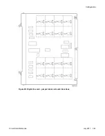
This section outlines the procedures for configuring the switches and jumpers on the NT8D02
Digital Line card and configuring the system software to properly recognize the card.
98: Digital line card - jumper block and switch locations
on page 361 shows where the switches
and jumper blocks are located on this board.
Configuration
Circuit Card Reference
July 2011 359
Summary of Contents for 1000 Series
Page 1: ...Circuit Card Reference Nortel Communication Server 1000 7 0 NN43001 311 04 04 July 2011 ...
Page 20: ...20 Circuit Card Reference July 2011 ...
Page 30: ...Introduction 30 Circuit Card Reference July 2011 Comments infodev avaya com ...
Page 116: ...Option settings 116 Circuit Card Reference July 2011 Comments infodev avaya com ...
Page 143: ...Figure 25 CP PIV card front Physical description Circuit Card Reference July 2011 143 ...
Page 148: ...NT4N39AA CP Pentium IV Card 148 Circuit Card Reference July 2011 Comments infodev avaya com ...
Page 287: ...Figure 86 Clock Controller Option 3 Operation Circuit Card Reference July 2011 287 ...
Page 302: ...NT5K21 XMFC MFE card 302 Circuit Card Reference July 2011 Comments infodev avaya com ...
Page 346: ...NT6D80 MSDL card 346 Circuit Card Reference July 2011 Comments infodev avaya com ...
Page 353: ...Figure 96 NTDK16 DLC Functional description Circuit Card Reference July 2011 353 ...
Page 461: ...Figure 147 Paging trunk operation Applications Circuit Card Reference July 2011 461 ...
Page 462: ...NT8D15 E and M Trunk card 462 Circuit Card Reference July 2011 Comments infodev avaya com ...
Page 500: ...NTAK09 1 5 Mb DTI PRI card 500 Circuit Card Reference July 2011 Comments infodev avaya com ...
Page 512: ...NTAK10 2 0 Mb DTI card 512 Circuit Card Reference July 2011 Comments infodev avaya com ...
Page 534: ...NTAK79 2 0 Mb PRI card 534 Circuit Card Reference July 2011 Comments infodev avaya com ...
Page 550: ...NTBK22 MISP card 550 Circuit Card Reference July 2011 Comments infodev avaya com ...
Page 560: ...NTBK50 2 0 Mb PRI card 560 Circuit Card Reference July 2011 Comments infodev avaya com ...
Page 595: ...Figure 165 MGC block diagram Introduction Circuit Card Reference July 2011 595 ...
Page 662: ...NTRB21 DTI PRI DCH TMDI card 662 Circuit Card Reference July 2011 Comments infodev avaya com ...
Page 668: ...NTVQ01xx Media Card 668 Circuit Card Reference July 2011 Comments infodev avaya com ...
Page 700: ......

