Overload level
Signal levels exc7 dBm applied to the tip and ring cause distortion in speech
transmission.
Environmental specifications
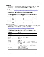
Table 166: Analog message waiting line card - environmental specifications
on page 373 lists
the environmental specifications for the analog message waiting line card.
Table 166: Analog message waiting line card - environmental specifications
Parameter
Specifications
Operating temperature
0° to +60° C (+32 to +140° F), ambient
Operating humidity
5 to 95% RH (non-condensing)
Storage temperature
–40° to +70° C (–40° to +158° F)
Connector pin assignments
The analog message waiting line card brings the 16 phone lines to the IPE backplane through
a 160-pin connector shroud. The backplane is cabled to the I/O panel on the rear of the module,
which is then connected to the MDF by 25-pair cables.
Telephone lines from station equipment cross connect to the analog message waiting line card
at the MDF using a wiring plan similar to that used for trunk cards. A typical connection example
is shown in
Figure 101: Analog message waiting line card - typical cross connection
Table 167: Analog message waiting line card - backplane
on page 374shows the I/O pin designations at the backplane connector. This
connector is arranged as an 80-row by 2-column array of pins. Normally, these pin positions
are cabled to 50-pin connectors at the I/O panel in the rear of each module for connection with
25-pair cables to the cross-connect terminal.
The information in
Table 167: Analog message waiting line card - backplane pinouts
page 374is provided as a reference and diagnostic aid at the backplane, because the cabling
arrangement may vary at the I/O panel. See
Communication Server 1000M and Meridian 1
Large System Installation and Configuration
(NN43021-310) for cable pinout information at the
I/O panel.
Connector pin assignments
Circuit Card Reference
July 2011 373
Summary of Contents for 1000 Series
Page 1: ...Circuit Card Reference Nortel Communication Server 1000 7 0 NN43001 311 04 04 July 2011 ...
Page 20: ...20 Circuit Card Reference July 2011 ...
Page 30: ...Introduction 30 Circuit Card Reference July 2011 Comments infodev avaya com ...
Page 116: ...Option settings 116 Circuit Card Reference July 2011 Comments infodev avaya com ...
Page 143: ...Figure 25 CP PIV card front Physical description Circuit Card Reference July 2011 143 ...
Page 148: ...NT4N39AA CP Pentium IV Card 148 Circuit Card Reference July 2011 Comments infodev avaya com ...
Page 287: ...Figure 86 Clock Controller Option 3 Operation Circuit Card Reference July 2011 287 ...
Page 302: ...NT5K21 XMFC MFE card 302 Circuit Card Reference July 2011 Comments infodev avaya com ...
Page 346: ...NT6D80 MSDL card 346 Circuit Card Reference July 2011 Comments infodev avaya com ...
Page 353: ...Figure 96 NTDK16 DLC Functional description Circuit Card Reference July 2011 353 ...
Page 461: ...Figure 147 Paging trunk operation Applications Circuit Card Reference July 2011 461 ...
Page 462: ...NT8D15 E and M Trunk card 462 Circuit Card Reference July 2011 Comments infodev avaya com ...
Page 500: ...NTAK09 1 5 Mb DTI PRI card 500 Circuit Card Reference July 2011 Comments infodev avaya com ...
Page 512: ...NTAK10 2 0 Mb DTI card 512 Circuit Card Reference July 2011 Comments infodev avaya com ...
Page 534: ...NTAK79 2 0 Mb PRI card 534 Circuit Card Reference July 2011 Comments infodev avaya com ...
Page 550: ...NTBK22 MISP card 550 Circuit Card Reference July 2011 Comments infodev avaya com ...
Page 560: ...NTBK50 2 0 Mb PRI card 560 Circuit Card Reference July 2011 Comments infodev avaya com ...
Page 595: ...Figure 165 MGC block diagram Introduction Circuit Card Reference July 2011 595 ...
Page 662: ...NTRB21 DTI PRI DCH TMDI card 662 Circuit Card Reference July 2011 Comments infodev avaya com ...
Page 668: ...NTVQ01xx Media Card 668 Circuit Card Reference July 2011 Comments infodev avaya com ...
Page 700: ......


