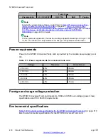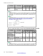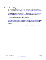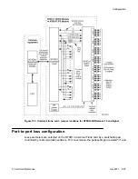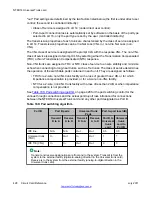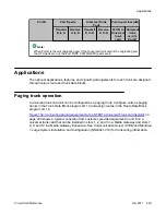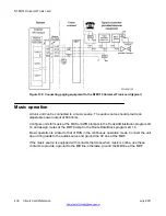
RAN machine. Multi-Channel RAN routes do not support the cross connecting (daisy chains)
of multiple trunk ports together so that several callers hear the same RAN message.
Multi-channel machine types - Continuous Mode Multi-Channel (MCON), Pulse Start/Stop
Multi-Channel (MPUL) and Level Start/Stop Multi-Channel (MLVL) – are not linked to a RAN
machine or a given trunk. All trunks belonging to the RAN route are considered independent.
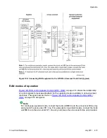
RAN trunks and RAN machine channels are connected one-to-one. If one RAN trunk is
detected as faulty, then all other trunks are not impacted.
For the RAN machine types, the maximum length of the recorded announcement is two hours.
The meaning of a ground signal received from the RAN machine (play or idle) is configured in
LD 16.
Multi-Channel Level Start/Control Mode (minimum vintage BA)
A RAN mode of operation is available called "Multi-Channel Level Start/Control Mode." This
mode enables provisioning of multiple RAN channels for a RAN route (playing the same
message independently on demand) cross-connected one-to-one to each RAN trunk in a multi-
channel level start RAN route. Do not bridge RAN trunks in a multi-channel RAN route.
The Route Data Block LD 16 is used to configure a RAN route in Multi-Channel Level Start/
Control mode, using the following response:
RTYP = MLSS
Trunk members are provisioned in the Trunk Data Block LD 14.
on page 416 and to
Software Input/Output Reference —
Administration
(NN43001-611) for instructions on service change programs.
Continuous operation mode
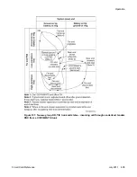
In the continuous operation mode (sometimes called the Audichron mode), a message is
constantly played, over and over again. Callers "barge in" on a playing message or receive a
ringback tone until the message plays again. The start line (ST+) is hardwired as always active.
See
Figure 129: RAN control signals (Control GRD = IDLE)
on page 414. At the end of each
message, a pulse is issued on the "C" line that is used by the trunk unit to cut through to the
waiting call.
Note:
The "B" (busy) signal line indicates availability of an announcement machine message to
the trunk unit when configured for the continuous operation mode. This signal is made active
(ground) by the announcement machine if the channel contains a recorded message and is
in an online condition. The "B" line is not connected to a trunk unit when configured for start
mode operation.
Start modes (minimum vintage BA)
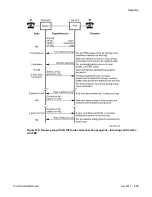
In a start mode (sometimes called the Code-a-Phone or start-stop mode), playback of a
message does not begin until a start pulse is received by the announcement machine. Two
subcategories of the start mode exist: pulse start and level start.
Operation
Circuit Card Reference
July 2011 415
Summary of Contents for 1000 Series
Page 1: ...Circuit Card Reference Nortel Communication Server 1000 7 0 NN43001 311 04 04 July 2011 ...
Page 20: ...20 Circuit Card Reference July 2011 ...
Page 30: ...Introduction 30 Circuit Card Reference July 2011 Comments infodev avaya com ...
Page 116: ...Option settings 116 Circuit Card Reference July 2011 Comments infodev avaya com ...
Page 143: ...Figure 25 CP PIV card front Physical description Circuit Card Reference July 2011 143 ...
Page 148: ...NT4N39AA CP Pentium IV Card 148 Circuit Card Reference July 2011 Comments infodev avaya com ...
Page 287: ...Figure 86 Clock Controller Option 3 Operation Circuit Card Reference July 2011 287 ...
Page 302: ...NT5K21 XMFC MFE card 302 Circuit Card Reference July 2011 Comments infodev avaya com ...
Page 346: ...NT6D80 MSDL card 346 Circuit Card Reference July 2011 Comments infodev avaya com ...
Page 353: ...Figure 96 NTDK16 DLC Functional description Circuit Card Reference July 2011 353 ...
Page 461: ...Figure 147 Paging trunk operation Applications Circuit Card Reference July 2011 461 ...
Page 462: ...NT8D15 E and M Trunk card 462 Circuit Card Reference July 2011 Comments infodev avaya com ...
Page 500: ...NTAK09 1 5 Mb DTI PRI card 500 Circuit Card Reference July 2011 Comments infodev avaya com ...
Page 512: ...NTAK10 2 0 Mb DTI card 512 Circuit Card Reference July 2011 Comments infodev avaya com ...
Page 534: ...NTAK79 2 0 Mb PRI card 534 Circuit Card Reference July 2011 Comments infodev avaya com ...
Page 550: ...NTBK22 MISP card 550 Circuit Card Reference July 2011 Comments infodev avaya com ...
Page 560: ...NTBK50 2 0 Mb PRI card 560 Circuit Card Reference July 2011 Comments infodev avaya com ...
Page 595: ...Figure 165 MGC block diagram Introduction Circuit Card Reference July 2011 595 ...
Page 662: ...NTRB21 DTI PRI DCH TMDI card 662 Circuit Card Reference July 2011 Comments infodev avaya com ...
Page 668: ...NTVQ01xx Media Card 668 Circuit Card Reference July 2011 Comments infodev avaya com ...
Page 700: ......


