Important:
Removing the utility card for maintenance and then re-inserting it could result in a PFTS for
a period of milliseconds. This may cause a power fail transfer box to activate if you have not
disabled the card for maintenance service. You can remove the utility card without causing
loss of service, however it can cause a loss of ringing and message waiting. Removing the
utility card does not prevent an outgoing call, but prevents an incoming analog call.
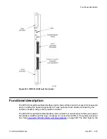
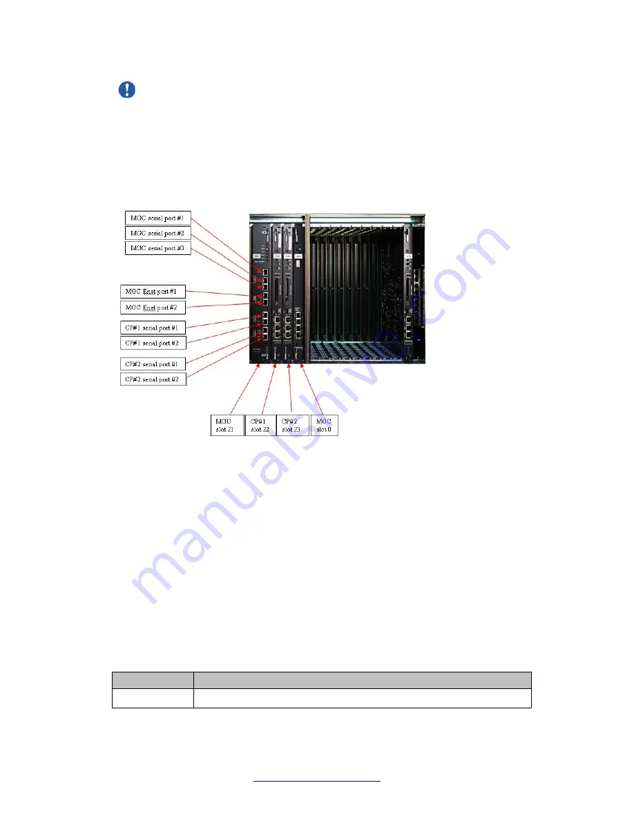
Figure 200: NTC314AAE6 utility card
The utility card supports all international requirements for message waiting voltages as well as
ringing requirements. A dip switch is required on this card for various country requirements.
The utility card is also hot-pluggable, thus you can connect it with the system turned on.
There are five tri-colour LEDs on the faceplate. Three LEDs are for the blowers and indicate
green as normal, orange as running at full speed, and red as a failure. The other two LEDs
provide the status of the power supplies with green being normal and red or extinguished
indicating a partial or full failure. The power supply LEDs are directly controlled by the power
supplies while the blower LEDs are controlled by controller circuitry on the blower modules.
The following tables describe the LED states for the power supply, blowers, and ringing and
message waiting.
Table 269: Power supply LED states
LED Color
Status
Green
Normal
NTC314AAE6 Media Gateway utility card
670 Circuit Card Reference
July 2011
Summary of Contents for 1000 Series
Page 1: ...Circuit Card Reference Nortel Communication Server 1000 7 0 NN43001 311 04 04 July 2011 ...
Page 20: ...20 Circuit Card Reference July 2011 ...
Page 30: ...Introduction 30 Circuit Card Reference July 2011 Comments infodev avaya com ...
Page 116: ...Option settings 116 Circuit Card Reference July 2011 Comments infodev avaya com ...
Page 143: ...Figure 25 CP PIV card front Physical description Circuit Card Reference July 2011 143 ...
Page 148: ...NT4N39AA CP Pentium IV Card 148 Circuit Card Reference July 2011 Comments infodev avaya com ...
Page 287: ...Figure 86 Clock Controller Option 3 Operation Circuit Card Reference July 2011 287 ...
Page 302: ...NT5K21 XMFC MFE card 302 Circuit Card Reference July 2011 Comments infodev avaya com ...
Page 346: ...NT6D80 MSDL card 346 Circuit Card Reference July 2011 Comments infodev avaya com ...
Page 353: ...Figure 96 NTDK16 DLC Functional description Circuit Card Reference July 2011 353 ...
Page 461: ...Figure 147 Paging trunk operation Applications Circuit Card Reference July 2011 461 ...
Page 462: ...NT8D15 E and M Trunk card 462 Circuit Card Reference July 2011 Comments infodev avaya com ...
Page 500: ...NTAK09 1 5 Mb DTI PRI card 500 Circuit Card Reference July 2011 Comments infodev avaya com ...
Page 512: ...NTAK10 2 0 Mb DTI card 512 Circuit Card Reference July 2011 Comments infodev avaya com ...
Page 534: ...NTAK79 2 0 Mb PRI card 534 Circuit Card Reference July 2011 Comments infodev avaya com ...
Page 550: ...NTBK22 MISP card 550 Circuit Card Reference July 2011 Comments infodev avaya com ...
Page 560: ...NTBK50 2 0 Mb PRI card 560 Circuit Card Reference July 2011 Comments infodev avaya com ...
Page 595: ...Figure 165 MGC block diagram Introduction Circuit Card Reference July 2011 595 ...
Page 662: ...NTRB21 DTI PRI DCH TMDI card 662 Circuit Card Reference July 2011 Comments infodev avaya com ...
Page 668: ...NTVQ01xx Media Card 668 Circuit Card Reference July 2011 Comments infodev avaya com ...
Page 700: ......


