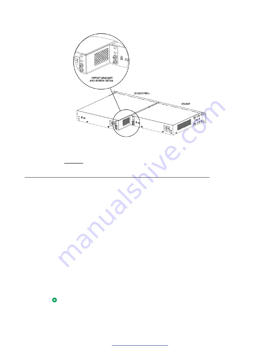
6. Slide the switches into the rack. Insert and tighten the rack mount screws.
7. Verify that the switch is securely fastened to the rack.
Installing the ERS 3524GT, ERS 3524GT-PWR+, ERS 3526T, or ERS
3526T-PWR+ switch in an equipment rack
Before you begin
Tool requirements
• a Phillips screwdriver to attach brackets to the switch and the switch to the rack.
Rack requirements
• space of 2.8 inches (7.1 cm) (or one vertical rack width) for each switch in an E1A or 1EC
standard 19 inch (48.2 cm) equipment rack and T1A 23 inch (58.5 cm) equipment rack.
• appropriate rack space to accommodate 1U switch height (44 mm).
• rack bolted to floor and braced if necessary
• rack must be grounded to the same grounding electrode used by the power service in the
area. The group path must be permanent and must not exceed 1 Ohm of resistance from
the rack to the grounding electrode.
Perform the following procedure to install your switch in an equipment rack.
Note:
The Avaya ERS 3500 Series hardware can vary in size and shape. Your switch might appear
different than the following example figures.
English
30 Regulatory Information 5.0
February 2012


