background image

Inserting or removing a compact flash memory card

03-603203 Issue 1 May 2009

11


Inserting or removing a compact flash memory card

The G450 and G430 support hot insertion and removal of a compact flash memory card without 
power drop, provided the compact flash is not in use when you remove it.

Inserting a compact flash memory card

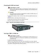
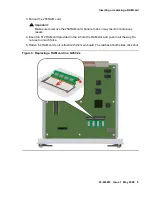
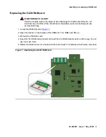
1. Remove the blank plate covering the compact flash memory card slot, located in the center 

of the main board.

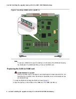
2. Position the compact flash memory card so that the vendor name is facing up and the 

connector is pointing toward the gateway, and gently insert it into the compact flash slot. 

3. After installing the compact flash memory card and the additional 256 MB RAM card, the 

announcement files are not automatically moved from the internal flash to the compact 
flash. To move them:

a. Make sure the gateway is registered to CM. 

b. At the CM, set 

enable CF

 to 

y

 in the 

change media-gateway 

screen.

c. In the SAT interface of the CM, enter 

enable announcement-board

The announcement files are copied from internal flash to the compact flash, and the 
yellow CARD IN USE LED associated with the compact flash lights up. 
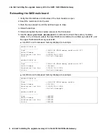
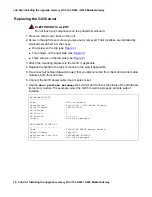
4. Use the 

show platform mainboard

 gateway CLI command to check the compact flash 

status. Sample output includes:

Removing a compact flash memory card

After installing a compact flash memory card, you may decide to remove it for one of several 
reasons. The following sections provide instructions for safe removal of a compact flash 
memory card in each possible scenario.

Replacing a compact flash memory card with a different compact flash memory card


holding a different set of announcements

COMPACT FLASH MEMORY

--------------------

Type 

: 2.0 GB

Serial Number  : STI1M28407353000355

Model Number 

: STI Flash 8.0.0

Faults : 

OK

Summary of Contents for 700457013

Page 1: ...act flash This also increases the total amount of announcement time from 45 minutes to four hours Since the announcements are played from RAM you must also increase RAM The upgrade memory kit consists of 1 GB compact flash memory card Two RAM cards Use the RAM card applicable to your gateway as detailed below The following sections describe the steps required to install or remove the upgrade memor...

Page 2: ...AM slots The basic configuration includes one 256 MB RAM card The slots are located on the G450 main board You must pull out the main board to remove or insert a memory card The G450 supports hot insertion and removal of the main board without power drop However all services are suspended while the G450 main board is out and all calls passing through the gateway are disconnected Any translation an...

Page 3: ...ure 1 2 Open the latches on both sides of the main board 3 Grasp the latches and pull out the main board from its slot 4 Place the main board carefully on a flat surface Figure 1 Removing and inserting the main board Inserting a G450 1 x RAM card ELECTROSTATIC ALERT ELECTROSTATIC ALERT Hold the module only by its edges to avoid damage from static electricity Do not touch the top or bottom of the c...

Page 4: ...he RAM slot housing the RAM card The RAM card lifts up Pull out the RAM card Replacing the G450 2 x RAM card ELECTROSTATIC ALERT ELECTROSTATIC ALERT Hold the module only by its edges to avoid damage from static electricity Do not touch the top or bottom of the circuit board If possible wear a wrist strap and use an anti static bag 1 Locate the RAM slot holding the RAM card see Figure 7 2 Open the ...

Page 5: ...remove the 256 RAM card Failure to do so may result in continuous resets 4 Insert the 512 RAM card provided in the kit into the RAM slot and push in all the way Do not use too much force 5 Flatten the RAM card so it is flush with the main board The latches at both sides click shut Figure 3 Replacing a RAM card in a G450 2 x ...

Page 6: ...the lower RAM slot is referred to as Memory socket 1 and the upper RAM slot is Memory socket 2 A G450 1 x with increased memory displays for example A G450 2 x with increased memory displays for example MEMORY SOCKET 1 Type 256MB DDR SDRAM memory module with ECC Serial Number 749f5c9f Manufacture Part Num 9VDDT3272AY 335G4 Faults No Fault Messages MEMORY SOCKET 2 Type 256MB DDR SDRAM memory module...

Page 7: ... the G430 from the external power source before proceeding ELECTROSTATIC ALERT ELECTROSTATIC ALERT Do not touch any components on the printed circuit board 1 Disconnect the G430 power cable from the mains power supply 2 Disconnect all cables data and power connected to the G430 and its media modules both front and rear Note to which connector each cable is connected so that you can reconnect them ...

Page 8: ...a Gateway Figure 4 Removing the G430 cover screw from the top of the device Figure notes 1 G430 top cover screw Figure 5 Removing G430 cover screws from the right side Figure notes 1 4 Four G430 right side cover screws Figure 6 Removing G430 cover screws from the left side Figure notes 1 3 Three G430 left side cover screws 1 1 4 2 3 1 2 3 ...

Page 9: ...cuit board If possible wear a wrist strap and use an anti static bag 1 Locate the RAM slot see Figure 7 2 Open the latches on both sides of the RAM slot The RAM card lifts up 3 Pull out the 256 RAM card 4 Insert the 512 RAM card provided in the kit into the RAM slot and push in all the way Do not use too much force 5 Flatten the RAM card so it is flush with the main board The latches at both sides...

Page 10: ...the mounting brackets to the G430 if applicable 4 Replace the G430 in the rack or mount on the wall if applicable 5 Re connect all cables data and power that you disconnected from the G430 and its media modules both front and rear 6 Connect the G430 power cable into a mains socket 7 Use the show platform mainboard CLI command to check the status of the G430 and its memory module For example when t...

Page 11: ...ernal flash to the compact flash To move them a Make sure the gateway is registered to CM b At the CM set enable CF to y in the change media gateway screen c In the SAT interface of the CM enter enable announcement board The announcement files are copied from internal flash to the compact flash and the yellow CARD IN USE LED associated with the compact flash lights up 4 Use the show platform mainb...

Page 12: ...e the yellow CARD IN USE LED associated with the compact flash is not flashing WARNING WARNING If a compact flash is removed while it is in use the announcement files on the compact flash may become corrupted and the gateway may reset causing all announcement files in RAM to be lost 3 Remove the compact flash memory card 4 Insert the new compact flash memory card into the compact flash slot 5 At t...

Page 13: ...ile usb to copy them one by one 2 At the SAT interface of the CM enter disable announcement board and then set enable CF to n in the change media gateway screen 3 Remove the compact flash memory card 4 Optionally remove the second RAM card 5 At the SAT interface of the CM enter enable announcement board 6 Make sure there are no more than 256 announcement files in the backup If the number of announ...

Page 14: ...Job Aid Installing the upgrade memory kit in the G450 G430 Media Gateway 14 Job Aid Installing the upgrade memory kit in the G450 G430 Media Gateway ...

Reviews: