background image

Chapter 3 Installing the base telephone equipment

39

Avaya 7406E Digital Mobile Handset Installation and Configuration Guide

4

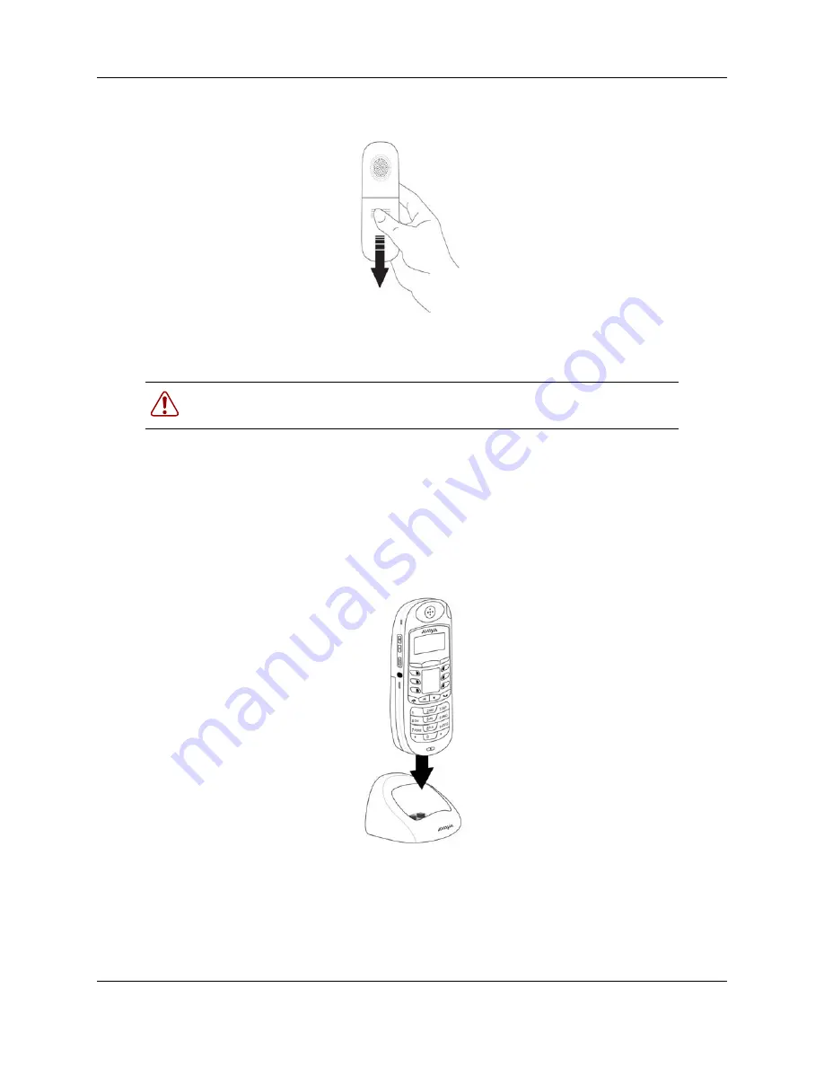
Replace the battery compartment cover.

Charging the battery pack for the first time

You must fully charge the rechargeable battery pack before you use your Avaya 7406E Digital 
Mobile Handset for the first time. 

1

Slide the handset into the charger, making sure the handset and charger contacts touch.

Charging begins as soon as the handset is placed in the charging cradle. The logo at the front 
of the charging cradle lights up to indicate that the handset is properly seated and charging.

2

Allow the battery pack to charge for a minimum of three hours.

Warning: 

It is imperative that you follow the steps in this section when you first 

initialize a base station and configure the first handset.

Summary of Contents for 7406E

Page 1: ...Avaya Business Communications Manager Document Status Standard Document Number NN40110 301 Document Version 02 02 Date June 2010 Avaya 7406E Digital Mobile Handset Installation and Configuration Guide ...

Page 2: ...RIZING OTHERS TO DO SO YOU ON BEHALF OF YOURSELF AND THE ENTITY FOR WHOM YOU ARE INSTALLING DOWNLOADING OR USING THE SOFTWARE HEREINAFTER REFERRED TO INTERCHANGEABLY AS YOU AND END USER AGREE TO THESE TERMS AND CONDITIONS AND CREATE A BINDING CONTRACT BETWEEN YOU AND AVAYA INC OR THE APPLICABLE AVAYA AFFILIATE AVAYA Copyright Except where expressly stated otherwise no use should be made of the Doc...

Page 3: ...1 20 name directory 12 Battery level indicator 12 Base station features 12 Wall or ceiling mountable 12 Colored LED status indicators 12 Security and encryption 12 Antenna diversity 13 USB to UART bridge controller 13 Chapter 2 Introduction 15 Specifications 15 Installation considerations 16 Operational bandwidths 16 Radio frequency local area networks 16 Operational parameters 17 Telephone to bas...

Page 4: ... upgrade components 34 USB to UART bridge controller 34 Handset adapter 34 Upgrade cables 35 Upgrade CD 36 Chapter 3 Installing the base telephone equipment 37 Important first time installation information 37 Before you start 37 Tools and materials 38 Chapter 4 Registering deregistering and resetting the Avaya 7406E Digital Mobile Handset 41 Chapter 5 Maintenance mode 47 Maintenance mode 47 Chapte...

Page 5: ...Contents 5 Avaya 7406E Digital Mobile Handset Installation and Configuration Guide Button mapping 57 ...

Page 6: ...6 Contents NN40110 301 NN40110 301 ...

Page 7: ...lling the external battery charger 38 Setting the base station DIP switches for a single base station application 39 Setting the base station DIP switches for a two base station application 39 Assigning a port ID to a handset 40 Registering a handset 41 Deregistering one handset 42 Deregistering all the handsets 42 Resetting a handset 43 Changing the maintenance password 43 Scanning the base stati...

Page 8: ...8 Task List NN40110 301 NN40110 301 ...

Page 9: ...and release notes directly from the Internet go to www avaya com support Getting product training Ongoing product training is available For more information or to register you can access the Web site at www avaya com support From this Web site you can locate the Training contacts link on the left hand navigation pane Getting help from a distributor or reseller If you purchased a service contract f...

Page 10: ...10 Customer service NN40110 301 NN40110 301 ...

Page 11: ...bile Handset features Three line LCD The LCD shows three rows of text with a maximum of 16 characters in each row The LCD also supports the English French and Spanish menus The LCD is back lit to help with viewing under low light conditions For more information on the LCD refer to the Avaya 7406E Digital Mobile Handset User Guide NN40110 110 One touch indicator keys You can program the indicator k...

Page 12: ...l Mobile Handset User Guide NN40110 110 Base station features This section describes some of the new Avaya 7406E Digital Mobile Handset base station features Wall or ceiling mountable The base station comes with a mounting rack that you can use to attach the base station to the wall or ceiling For more information on how to mount the base station on the wall or ceiling refer to Securing the base s...

Page 13: ...djust the antenna for optimal transmission by moving it through 90 degree angle planes for example perpendicular to the wall parallel to the wall perpendicular to the floor parallel to the floor USB to UART bridge controller You can upgrade the Avaya 7406E Digital Mobile Handset firmware when new versions become available Use the USB to UART bridge controller along with the FlashLoader program to ...

Page 14: ...14 Chapter 1 New in this release NN40110 301 NN40110 301 ...

Page 15: ...U The handset features are easy to set up using the function key and menus Specifications The Avaya 7406E Digital Mobile Handset is a frequency hopping spread spectrum FHSS cordless telephone The base station connects to the Avaya KSU Avaya Norstar CICS and MICS and Avaya Business Communications Manager Avaya BCM systems The benefits of this technology are improved range robustness and less suscep...

Page 16: ...F LAN are primarily installed in large chain businesses such as retail and grocery where the RF LAN is used for inventory equipment With the correct selection of the Avaya 7406E Digital Mobile Handset operating band the RF LAN operating at 2 4 GHz does not pose an operating issue for Avaya 7406E Digital Mobile Handset nor does the Avaya 7406E Digital Mobile Handset pose issues for the RF LAN with ...

Page 17: ...vironment for obstructions that can limit the range Change the orientation of the base station antenna Move the base station to another location Select the alternate operating band of the Avaya 7406E Digital Mobile Handset Based on environmental characteristics the Avaya 7406E Digital Mobile Handset may not be the optimum solution for all users If the desired level of mobility performance is not m...

Page 18: ...e base station a minimum of eight feet from the floor Minimize the number of walls between the base station and handsets Centralize the location of the base station to make the number of interfering walls equal in all directions Do not mount the base station on an outside wall Do not mount or place the base station outdoors Adjust the antenna for optimal transmission by moving it through 90 degree...

Page 19: ...d utility rooms in the core facility Some transmission path loss occurs when the base station and the handset are separated by physical barriers as represented by this core area The amount of path loss is depends on the number of walls type of material and density of barriers used in the core area Combination office warehouse Various small businesses Typically under 1 394 square meters 15 000 squa...

Page 20: ...he Avaya 7406E Digital Mobile Handset handset automatically links with the base station by searching for the base station signal after you complete following tasks charge the battery power the base station and handset configure the handset identification Monitoring handset signal strength When you move too far from the base station the following occurs on the handset the Out of range message appea...

Page 21: ...ion 21 Avaya 7406E Digital Mobile Handset Installation and Configuration Guide Handset features Figure 1 on page 22 shows the layout of the handset function keys softkeys and keypad as well as additional handset features ...

Page 22: ...cels active calls Soft keys Use in Programming mode to scroll through menus and options Microphone Headset port Volume control Dial pad Battery Pack Call hold message waiting indicator Flashes when a call is on hold or when a message is waiting Func key Use to access programming mode or to answer a call Feature key Activates the Feature functions Belt clip notches Handsfree speaker phone Hold Plac...

Page 23: ... available when the phone is in system programming mode Navigating through programming mode menus Complete this procedure to learn how to scroll up and down through the main menu and up and down through menu options 1 Press the Func key to enter system programming mode The main menu appears 2 Use the ïï ïïïïïï and ïïïï softkeys to scroll through the main menu 3 At any menu level press the Release ...

Page 24: ... Add Down Edit Dial Down Bksp Save Space Back Name Next Back Number Next Back Remove Done Key Lock Key locked Key unlock Select Message LED On Off Back Light 60sec 50sec 40sec 30sec 20sec 10sec Off Key Beep Off On Ring Vibration Ring On Both Off Both On Vibration On Ring Type Type 1 Type 2 Type 3 Type 4 Type 5 Type 6 Type 7 Type 8 Ring Level High Medium Low ...

Page 25: ...battery pack see Chapter 3 Installing the base telephone equipment on page 37 You must fully charge the rechargeable battery pack before you use the Avaya 7406E Digital Mobile Handset for the first time Default Volume Level 8 Level 7 Level 6 Level 5 Level 4 Level 3 Level 2 Level 1 No Default Noisy Location Level 1 Level 2 Level 3 Level 4 Display Battery Voltage Level Maintenance Enter Pswd Assign ...

Page 26: ...s You can use the handset for an entire eight hour work day without putting it into the charger cradle for charging or topping up You can use a handset with a fully charged battery for four to five hours of talk time Most users do not use more than three hours of talk time in an average eight hour work day If talk time exceeds four hours or if you use the handset through multiple consecutive shift...

Page 27: ...ed the LED turns green It takes approximately 5 hours for a depleted battery pack to be completely recharged Base station overview This section illustrates the base station for the Avaya 7406E Digital Mobile Handset system see Figure 3 on page 28 You can mount the base station on a wall or on the ceiling or place it on a flat surface without the mounting bracket See Chapter 3 Installing the base t...

Page 28: ...operation the LED flashes every second to indicate that the base station is receiving power Figure 4 on page 29 shows the location of the LEDs You can use the mounting bracket to install the base station on a wall or on the ceiling see Figure 5 on page 29 Figure 3 Base station Base station antennas 90 to base station LED indicates base station has power LEDs indicate handset status ...

Page 29: ...uction 29 Avaya 7406E Digital Mobile Handset Installation and Configuration Guide Figure 4 Base station LEDs Figure 5 Base station with mounting bracket Power LED Channel LEDs Mounting bracket Notches match to bracket ...

Page 30: ...mode full band band A for optional two band setup band B for optional two band setup registration mode deregistration mode all handsets If you install two base stations and there is interference between the two when in normal operating most you can set one base station to operate in the band A upper band and the other base station to operate in band B lower band For the DIP switch settings for eac...

Page 31: ...Handset Installation and Configuration Guide Figure 6 Back of base station showing DIP switches Wiring charts For information how to wire the Avaya 7406E Digital Mobile Handset to your system refer to Appendix B Wiring information on page 55 DIP switches ...

Page 32: ...y managing two critical elements in the battery charging process charge rate and overcharging protection NiMh batteries do not exhibit memory problems You do not need to drain the batteries before you recharge them Low battery status is indicated on the handset by the visual charge status on the display and the audible warning tone The battery icon appears in the upper right hand corner of the han...

Page 33: ...l is automatically put on hold 20 seconds after the battery pack runs out Recharging the battery Recharging begins as soon as you put the handset in the charging cradle Refer to Charging the battery pack for the first time page 39 Be sure that the handset and charger contacts touch Battery levels The following icons appear on the display Note If you do not correctly install the Avaya 7406E Digital...

Page 34: ...troller has a UART port You connect the bridge controller to the upgrade jig or directly to the base station in the case of a base station upgrade using an upgrade cable The bridge controller is powered using the provided AC power source see Figure on page 34 Refer to Chapter 6 Upgrading the firmware on page 49 for details on how to upgrade the firmware on your Avaya 7406E Digital Mobile Handset a...

Page 35: ... with two cables and a power source Use the USB to UART cable to connect the bridge controller to your PC Use the upgrade cable to connect the bridge controller to the handset adapter or to the base station upgrade port Use the supplied AC power source to supply power to the base station or to the handset during the upgrade Spring loaded clips Handset adapter ...

Page 36: ...n upgrade port Upgrade CD The upgrade kit comes with an upgrade CD The upgrade CD contains the required upgrade device drivers one for the handset upgrade and one for the base station upgrade the FlashGUI upgrade interface and the upgrade firmware ToPC Upgrade Upgrade to handset adapter or to base station AC power cord Upgrade port ...

Page 37: ... the initial configurations on the handset ensure that all the handsets you intend to configure have fully charged battery packs installed Because the handsets start scanning as soon as they are powered you must set the handset IDs before you configure the handset to avoid conflicts between handset signals and the possibility of one set mirroring another For information on wiring your system refer...

Page 38: ...ed cables for RJ45 connector if you are installing more than one handset Installing the handset charging cradle 1 Plug the small end of the power adapter into the back of the charging cradle 2 Plug the other end of the power adapter into an AC outlet near the location of the cradle 3 Place the handset in the cradle to charge the battery Installing the battery pack Complete this procedure if the ba...

Page 39: ...e Handset for the first time 1 Slide the handset into the charger making sure the handset and charger contacts touch Charging begins as soon as the handset is placed in the charging cradle The logo at the front of the charging cradle lights up to indicate that the handset is properly seated and charging 2 Allow the battery pack to charge for a minimum of three hours Warning It is imperative that y...

Page 40: ...elephone port on the system equipment For wiring information refer to Appendix B Wiring information on page 55 3 Plug the small end of the power adapter into the back of the base station 4 Plug the other end of the power adapter into an AC outlet near the location of the base station Mounting the base station Complete this procedure if you plan to mount the base station on a wall or ceiling Skip t...

Page 41: ...returns to Normal mode no registrations after 30 seconds If the user wants to use a handset in Normal mode then the handset must be registered to the base in Normal mode Once completed successfully there is no registration issue after the base has been power cycled providing the dip switch settings are not rearranged A Group mode Allows the base station to be in Registration mode for the first 30 ...

Page 42: ...he base station DIP switches at the back of the second base station 4 Set the DIP switches to normal operating mode for a two base station application base station B The base stations each now operate in one half of the ISM band Assigning a port ID to a handset You cannot assign the same port ID to two handsets If you assign a handset a port ID that is already used by a second handset the new hand...

Page 43: ...the message Failed Try Again appears on the LCD You return to the top of the Maintenance menu Re enter the password If the password is correct the message OK appears on the LCD and you enter maintenance operation mode 6 Use the up and down softkeys to navigate to the Assign Port ID option 7 Press Select 8 Use the up and down softkeys to navigate to the port ID you want to assign 1 2 3 or 4 9 Press...

Page 44: ...e station to registration mode If you do nothing with the handset for more than 30 seconds when the system is in registration mode the system returns automatically to normal operation mode without you having to change the DIP switches 3 Log on to the Maintenance menu 4 Use the up and down softkeys to navigate to the Registration option 5 Press Select 6 Use the up and down softkeys to navigate to t...

Page 45: ...Log on to the Maintenance menu 2 Use the up and down softkeys to navigate to the De Registration option 3 Press Select 4 Use the up and down softkeys to navigate to the Yes option 5 Enter the port ID that is assigned to the handset 6 Press Select 7 Press OK The set is now registered Deregistering all the handsets Make sure the base station is in idle mode the handsets are in standby mode and that ...

Page 46: ...e to the Reset option 5 Select yes to reset the handset The Resetting Please Wait message appears in the LCD The handset returns to default status The handset restarts and the Initializing Please Wait message appears in the LCD The Please Register message appears Changing the maintenance password 1 Log on to the Maintenance menu using the default password 000000 2 Use the up and down softkeys to n...

Page 47: ...nment Maintenance mode Complete the following activities in maintenance mode Scanning the base station radio frequency You must register the handset with a base station before you can perform this procedure 1 Press the Func key to enter system programming mode The main menu appears 2 Use the ïï ïïïïïï and ïïïï softkeys to navigate to the Maintenance menu 3 Press Select 4 Log on to the Maintenance ...

Page 48: ...anning the environment 1 Log on to the Maintenance menu 2 Use the up and down softkeys to navigate to the Scan Environment option 3 Press Select 4 Use the up and down softkeys to navigate to the Yes option The handset scans the environment for signal status ...

Page 49: ... have removed power from the base station Tools and materials Before you upgrade the firmware of the base station and the handsets ensure that you have the following tools and materials package contents Avaya 7406E Digital Mobile Handset upgrade bridge controller handset adapter AC power cord USB to UART cable upgrade cable CD containing USB to UART bridge controller drivers Installing the USB to ...

Page 50: ...roller and the PC The PC LED lights 4 Connect the upgrade cable between the upgrade ports of the bridge controller and the base station The power LED on the base station lights 5 On your PC right click on My Computer 6 Navigate to Properties Hardware Device Manager Ports USB to UART Bridge Controller COMx 7 Make note of the port COM number COM1 COM2 COM3 for example 8 From the upgrade CD launch th...

Page 51: ...firmly into the battery pack compartment at the back of the handset 8 Release the levers to allow the handset adapter jig to snap firmly into place 9 On your PC right click on My Computer 10 Navigate to Properties Hardware Device Manager Ports USB to UART Bridge Controller COMx 11 Make note of the port COM number COM1 COM2 COM3 for example 12 From the upgrade CD launch the FlashLoaderGUI exe execu...

Page 52: ... procedure for each additional handset Verifying the firmware version Complete this procedure to ensure that the new firmware is properly installed 1 Ensure that the base station has power 2 Wait for the base station power LED to turn green 3 On an upgraded handset press the Function key 4 Navigate to the Maintenance menu Do not enter the password to log on 5 Use the dialpad to enter AVAYA 6 Press...

Page 53: ...Handset base station There are five DIP switch settings that you can use to configure the system Figure 13 DIP switch location on base station Table 6 DIP switch settings Mode DIP switch 1 DIP switch 2 DIP switch 3 Normal operation Down Down Down Two base A channel Up Down Down Two base B channel Down Up Down Registration mode Down Down Up Deregistration mode Up Up Up Dip switches ...

Page 54: ...54 Appendix A DIP switch settings NN40110 301 NN40110 301 ...

Page 55: ...specific wiring to your system Refer to Figure 15 on page 55 to properly wire your Avaya 7405E Digital Mobile Handset Refer for Figure 14 RJ45 pinout and TCM loops Figure 15 Cable pairs Table 7 Cable pair descriptions Cable pair Cable number Color code 1 1 Blue White 1 2 Blue 2 3 Orange White 2 4 Orange 3 5 Green White 1 2 3 4 5 6 7 8 1 2 3 4 TCM loops ...

Page 56: ...56 Appendix B Wiring information NN40110 301 NN40110 301 3 6 Green 4 7 Red White 4 8 Red Table 7 Cable pair descriptions Cable pair Cable number Color code ...

Page 57: ... usual mapping of the buttons based on the M7310 telephone button mapping The illustration below shows examples of the default button mapping for the handset Figure 16 Avaya 7406E Digital Mobile Handset The following three illustrations show the correlation between the Avaya 7406E Digital Mobile Handset buttons and the M7310 Avaya 7316 Digital Mobile Handset and Avaya 7316E Digital Mobile Handset ...

Page 58: ...58 Appendix C Button mapping NN40110 301 NN40110 301 Figure 17 M7310 to Avaya 7406E Digital Mobile Handset button mapping Figure 18 Avaya 7316 to Avaya 7406E Digital Mobile Handset button mapping ...

Page 59: ...Appendix C Button mapping 59 Avaya 7406E Digital Mobile Handset Installation and Configuration Guide Figure 19 Avaya 7316E to Avaya 7406E Digital Mobile Handset button mapping ...

Page 60: ...60 Appendix C Button mapping NN40110 301 NN40110 301 ...

Reviews: