background image

©

 2015 Avaya Inc.

All Rights Reserved.

Notice

While reasonable efforts have been made to ensure that the

information in this document is complete and accurate at the time of

printing, Avaya assumes no liability for any errors. Avaya reserves

the right to make changes and corrections to the information in this

document without the obligation to notify any person or organization

of such changes.

Documentation disclaimer

“Documentation” means information published by Avaya in varying

mediums which may include product information, operating

instructions and performance specifications that Avaya may generally

make available to users of its products and Hosted Services.

Documentation does not include marketing materials. Avaya shall not

be responsible for any modifications, additions, or deletions to the

original published version of documentation unless such

modifications, additions, or deletions were performed by Avaya. End

User agrees to indemnify and hold harmless Avaya, Avaya's agents,

servants and employees against all claims, lawsuits, demands and

judgments arising out of, or in connection with, subsequent

modifications, additions or deletions to this documentation, to the

extent made by End User.

Link disclaimer

Avaya is not responsible for the contents or reliability of any linked

websites referenced within this site or documentation provided by

Avaya. Avaya is not responsible for the accuracy of any information,

statement or content provided on these sites and does not

necessarily endorse the products, services, or information described

or offered within them. Avaya does not guarantee that these links will

work all the time and has no control over the availability of the linked

pages.

Warranty

Avaya provides a limited warranty on Avaya hardware and software.

Refer to your sales agreement to establish the terms of the limited

warranty. In addition, Avaya’s standard warranty language, as well as

information regarding support for this product while under warranty is

available to Avaya customers and other parties through the Avaya

Support website: 

http://support.avaya.com

 or such successor site as

designated by Avaya. Please note that if You acquired the product(s)

from an authorized Avaya Channel Partner outside of the United

States and Canada, the warranty is provided to You by said Avaya

Channel Partner and not by Avaya.

Licenses

THE SOFTWARE LICENSE TERMS AVAILABLE ON THE AVAYA

WEBSITE, 

HTTP://SUPPORT.AVAYA.COM/LICENSEINFO

 OR

SUCH SUCCESSOR SITE AS DESIGNATED BY AVAYA, ARE

APPLICABLE TO ANYONE WHO DOWNLOADS, USES AND/OR

INSTALLS AVAYA SOFTWARE, PURCHASED FROM AVAYA INC.,

ANY AVAYA AFFILIATE, OR AN AVAYA CHANNEL PARTNER (AS

APPLICABLE) UNDER A COMMERCIAL AGREEMENT WITH

AVAYA OR AN AVAYA CHANNEL PARTNER. UNLESS

OTHERWISE AGREED TO BY AVAYA IN WRITING, AVAYA DOES

NOT EXTEND THIS LICENSE IF THE SOFTWARE WAS

OBTAINED FROM ANYONE OTHER THAN AVAYA, AN AVAYA

AFFILIATE OR AN AVAYA CHANNEL PARTNER; AVAYA

RESERVES THE RIGHT TO TAKE LEGAL ACTION AGAINST YOU

AND ANYONE ELSE USING OR SELLING THE SOFTWARE

WITHOUT A LICENSE. BY INSTALLING, DOWNLOADING OR

USING THE SOFTWARE, OR AUTHORIZING OTHERS TO DO SO,

YOU, ON BEHALF OF YOURSELF AND THE ENTITY FOR WHOM

YOU ARE INSTALLING, DOWNLOADING OR USING THE

SOFTWARE (HEREINAFTER REFERRED TO

INTERCHANGEABLY AS “YOU” AND “END USER”), AGREE TO

THESE TERMS AND CONDITIONS AND CREATE A BINDING

CONTRACT BETWEEN YOU AND AVAYA INC. OR THE

APPLICABLE AVAYA AFFILIATE (“AVAYA”).

Avaya grants You a license within the scope of the license types

described below, with the exception of Heritage Nortel Software, for

which the scope of the license is detailed below. Where the order

documentation does not expressly identify a license type, the

applicable license will be a Designated System License. The

applicable number of licenses and units of capacity for which the

license is granted will be one (1), unless a different number of

licenses or units of capacity is specified in the documentation or other

materials available to You. “Software” means computer programs in

object code, provided by Avaya or an Avaya Channel Partner,

whether as stand-alone products, pre-installed on hardware products,

and any upgrades, updates, patches, bug fixes, or modified versions

thereto. “Designated Processor” means a single stand-alone

computing device. “Server” means a Designated Processor that

hosts a software application to be accessed by multiple users.

“Instance” means a single copy of the Software executing at a

particular time: (i) on one physical machine; or (ii) on one deployed

software virtual machine (“VM”) or similar deployment.

License types

Designated System(s) License (DS). End User may install and use

each copy or an Instance of the Software only on a number of

Designated Processors up to the number indicated in the order.

Avaya may require the Designated Processor(s) to be identified in

the order by type, serial number, feature key, Instance, location or

other specific designation, or to be provided by End User to Avaya

through electronic means established by Avaya specifically for this

purpose.

Heritage Nortel Software

“Heritage Nortel Software” means the software that was acquired by

Avaya as part of its purchase of the Nortel Enterprise Solutions

Business in December 2009. The Heritage Nortel Software currently

available for license from Avaya is the software contained within the

list of Heritage Nortel Products located at 

http://support.avaya.com/

LicenseInfo

 under the link “Heritage Nortel Products” or such

successor site as designated by Avaya. For Heritage Nortel

Software, Avaya grants You a license to use Heritage Nortel

Software provided hereunder solely to the extent of the authorized

activation or authorized usage level, solely for the purpose specified

in the Documentation, and solely as embedded in, for execution on,

or for communication with Avaya equipment. Charges for Heritage

Nortel Software may be based on extent of activation or use

authorized as specified in an order or invoice.

Copyright

Except where expressly stated otherwise, no use should be made of

materials on this site, the Documentation, Software, Hosted Service,

or hardware provided by Avaya. All content on this site, the

documentation, Hosted Service, and the product provided by Avaya

including the selection, arrangement and design of the content is

owned either by Avaya or its licensors and is protected by copyright

and other intellectual property laws including the sui generis rights

relating to the protection of databases. You may not modify, copy,

reproduce, republish, upload, post, transmit or distribute in any way

any content, in whole or in part, including any code and software

unless expressly authorized by Avaya. Unauthorized reproduction,

transmission, dissemination, storage, and or use without the express

written consent of Avaya can be a criminal, as well as a civil offense

under the applicable law.

Third Party Components

“Third Party Components” mean certain software programs or

portions thereof included in the Software or Hosted Service may

contain software (including open source software) distributed under

third party agreements (“Third Party Components”), which contain

terms regarding the rights to use certain portions of the Software

(“Third Party Terms”). As required, information regarding distributed

Linux OS source code (for those products that have distributed Linux

OS source code) and identifying the copyright holders of the Third

Party Components and the Third Party Terms that apply is available

in the products, Documentation or on Avaya’s website at: 

http://

support.avaya.com/Copyright

 or such successor site as designated

by Avaya. You agree to the Third Party Terms for any such Third

Party Components.

Preventing Toll Fraud

“Toll Fraud” is the unauthorized use of your telecommunications

system by an unauthorized party (for example, a person who is not a

corporate employee, agent, subcontractor, or is not working on your

company's behalf). Be aware that there can be a risk of Toll Fraud

associated with your system and that, if Toll Fraud occurs, it can

Summary of Contents for 9010CM

Page 1: ...Installing Cooling Modules in Avaya Virtual Services Platform 9000 Release 4 0 NN46250 302 Issue 05 05 March 2015...

Page 2: ...ty is specified in the documentation or other materials available to You Software means computer programs in object code provided by Avaya or an Avaya Channel Partner whether as stand alone products p...

Page 3: ...problem with your Avaya product or Hosted Service For a list of support telephone numbers and contact addresses go to the Avaya Support website http support avaya com or such successor site as design...

Page 4: ...g modules 26 9012RC SF cooling module 27 Airflow in the Virtual Services Platform 9012 28 Temperature alarms 32 Data center floor plan 40 Optimizing cooling in a data center 41 Virtual Services Platfo...

Page 5: ...A electromagnetic interference warning statement 58 Electrostatic discharge caution statement 59 Cooling module fan safety danger statement 60 Glossary 62 Contents March 2015 Installing Cooling Modul...

Page 6: ...m 9012 uses the following two cooling module types when you configure second generation modules in second generation mode 2 x 9012FCHS cooling module 2 x 9012RC SF cooling module Note The Virtual Serv...

Page 7: ...vaya Support website listed under the video document type and on the Avaya run channel on YouTube Procedure To find videos on the Avaya Support website go to http support avaya com and perform one of...

Page 8: ...urrences of a particular feature Use this procedure to perform an index search of your documentation collection Before you begin Download the documentation collection zip file to your local computer Y...

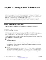
Page 9: ...and Temperature alarms on page 32 show sys info Release 4 0 updates the output for the show sys info command For more information see Temperature alarms on page 14 Temperature alarms on page 32 Other...

Page 10: ...zontally in the front of the chassis The cooling modules provide cooling from front to back for the Input Output IO the Control Processor CP and the Switch Fabric SF modules Each cooling module includ...

Page 11: ...the Avaya Virtual Services Platform 9000 NN46250 304 The following figure shows the Virtual Services Platform 9010 cooling module in a partially open position The following table identifies the numbe...

Page 12: ...ntrol of the module The Control Processor has lost communication to the fan Note A flashing amber light can appear when the cooling module fans have not reached the programmed speed Red Fault One or m...

Page 13: ...the hot air exhaust for the CP and I O modules is at the top The hot air exhaust for the SF modules is to the right of the SF module slots Figure 1 Front to back cooling in the Virtual Services Platf...

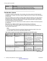
Page 14: ...n in the following table as a quick reference for temperature thresholds on the Virtual Services Platform 9010 Note The I O module alarm threshold and shutdown threshold temperatures differ for the Vi...

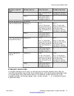
Page 15: ...dule when the module exceeds the shutdown threshold by one degree Green Alarm clears after the temperatures of the modules are at 89 C Fabric Adapter FA sensors Blinking red 105 C At 106 C the system...

Page 16: ...m mode If the module exceeds the shutdown threshold by one degree it causes the module to shut down The zone alarm is triggered after one of the following events occurs A module alarm is triggered Mod...

Page 17: ...on all the modules with the following command show sys info temperature Note The I O module alarm threshold and shutdown threshold temperatures differ for the Virtual Services Platform 9010 and the V...

Page 18: ...GA 47 51 52 55 56 55 52 59 58 59 47 90 95 7 FA 42 50 66 66 42 105 110 8 FPGA 67 51 52 55 53 52 55 57 61 67 51 90 95 8 FA 39 50 72 72 39 105 110 The following table describes the output for the show sy...

Page 19: ...wn Threshold Specifies the FPGA or FA temperature when exceeded by one degree that causes the system to shutdown the module by removing power from the slot Virtual Services Platform 9010 show sys info...

Page 20: ...1 OK FRONT FAN 2 2 OK FRONT FAN 2 3 OK FRONT FAN 2 4 OK Use the data in the following table to understand the output for the show sys info command on the Virtual Services Platform 9010 Value Descript...

Page 21: ...ys displays as Normal Highest Temperature For VSP 9010 no rear fan zone exists as a result the temperature always reports as 0 C Fan Info FAN 1 Specifies the module type under card type FAN 2 Specifie...

Page 22: ...ix of first and second generation I O modules expected behavior Two 9012FCHS I O cooling module First and second generation I O modules run as expected and only shut down if their thermal sensors exce...

Page 23: ...O cooling module slots to provide cooling for the I O modules and the Control Processor CP modules Each 9012FCHS cooling module includes eight fans and provides side to side cooling The minimum softw...

Page 24: ...time without turning off the Virtual Services Platform 9000 The following figure shows the 9012FCHS cooling module for the Virtual Services Platform 9012 Figure 3 9012FCHS cooling module partially rem...

Page 25: ...the second generation modules remain offline until you install the 9012FCHS cooling modules For more information about the 9012FCHS cooling module see 9012FCHS I O cooling module on page 23 The CP mo...

Page 26: ...250 8 millimeters 596 9 millimeters 28 6 millimeters 4 08 kilograms Front panel LED for the 9012FC and 9012FCHS I O cooling modules The 9012FC and the 9012FCHS I O cooling modules for the Virtual Ser...

Page 27: ...The fan tray may not provide enough cooling 9012RC SF cooling module The Virtual Services Platform 9012 requires two 9012RC SF cooling modules You must install the SF cooling modules in the back of th...

Page 28: ...2 9012RC SF cooling module LED status LED Color Status Description Green Normal Both fans are functional and spinning above the program controlled FAN_FAULT_THRESHOLD register settings Red Fail One or...

Page 29: ...iagram Description 1 I O module air inlet 2 Power supply fan air inlet 3 I O module air exhaust 4 9012FC or 9012FCHS cooling modules 5 Switch Fabric module air inlet 6 Airflow left to right Virtual Se...

Page 30: ...modules in second generation mode or first generation modules in first generation mode on the front right side of the Virtual Services Platform 9012 The 9012 cooling modules provide air movement and h...

Page 31: ...rm 9012 two fans exist in each 9012RC cooling module and pull air from front to back The platform polls all Switch Fabric module sensors and adjusts the 9012RC fan speed accordingly Note Do not place...

Page 32: ...d shutdown threshold temperatures differ for the Virtual Services Platform 9010 and the Virtual Services Platform 9012 Table 14 Alarm threshold and shutdown threshold temperatures for VSP 9012 modules...

Page 33: ...ule when the module exceeds the shutdown threshold by one degree Green Alarm clears after the temperatures of the modules are at 104 C Bringing the module online If a module shuts down due to heat you...

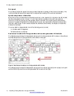
Page 34: ...first generation and second generation I O modules The following figure shows the baseboard component of a first generation I O module on the left and the PIM component of a first generation I O modul...

Page 35: ...e 5 address 96 The system monitors the temperature every 30 seconds and displays the temperature on all the modules with the following command show sys info temperature Note The I O module alarm thres...

Page 36: ...10 FA 41 49 64 64 41 105 110 The following table describes the output for the show sys info temperature command Value Description Temperature Info Zones 1 through 3 Specifies the inlet sensors on the...

Page 37: ...by removing power from the slot Virtual Services Platform 9012 show sys info output On the Virtual Services Platform 9012 you can see the zone alarm information under the Fan Trays Info section of th...

Page 38: ...12FCHS LBNNTMRJ000172 EC1411004 E6 IO FAN 2 9012FCHS LBNNTMRJ00015T EC1411004 E6 SF FAN 1 9012RC LBNNTMRJ000049 EC1411002 E6 SF FAN 2 9012RC LBNNTMRJ000046 EC1411002 E6 Zone Tray Unit Status FRONT IO...

Page 39: ...FA sensor located on the slice A value of indicates that this sensor is not available on this slot REAR zone For the VSP 9012 the rear zone consists of two fan trays with two fans in each tray which c...

Page 40: ...imizes airflow through the creation of hot aisles and cold aisles The cold aisles can have a raised floor which consists of tiles with perforations to allow cold air to enter the devices Figure 11 Dat...

Page 41: ...chassis to the left discharges hot air into the cool intake of the chassis to the right This installation does not optimize cool airflow Optimizing cooling in a data center To optimize left to right c...

Page 42: ...aisles 6 Cold aisle 8 to 13 Other equipment front to back cooling Virtual Services Platform 9012 placement in the rack If you place each Virtual Services Platform 9012 in a row from left to right the...

Page 43: ...rs versus non raised floors for cooling If you do not have raised floors for cooling you need to ensure air is injected into the cool intake at the left side You can add extra stand alone fans to ensu...

Page 44: ...management blocking fans 2 Fans Clearance Do not place the Virtual Services Platform 9012 chassis directly against a wall equipment or other obstruction Avaya recommends 36 inches 91 centimeters of fr...

Page 45: ...ssis Be careful not to bump module connectors against the action levers of an adjacent module Damage to connectors can result Use both hands to support modules Visually inspect the connectors for dama...

Page 46: ...the modules in the front of the chassis and also to the Switch Fabric in the back of the chassis Installation takes 2 to 5 minutes Removing the air inlet cover Before you can install or remove a power...

Page 47: ...e chassis You can hot swap the cooling modules Install the cooling modules horizontally in the front of the Virtual Services Platform 9010 Before you begin Remove the air inlet bezel Acquire the follo...

Page 48: ...ure 3 Slide the cooling module into the chassis until the cooling module is flush with the sides of the chassis The connector at the rear of the cooling module must connect to the midplane 4 Rotate th...

Page 49: ...ch electronic hardware unless you wear a grounding wrist strap or other static dissipating device Procedure 1 Loosen the captive screws that secure the cooling module to the midplane 2 Press the cooli...

Page 50: ...When you remove a cooling module allow time for the fans to spin down before you fully withdraw the cooling module Be careful to keep your fingers out of the fan blades as shown in the following figur...

Page 51: ...t the weight of the module 5 Grasp the cooling module on both sides midway between the front and rear fans to support the weight of the cooling module Continue to slide the module out of the chassis C...

Page 52: ...ling modules Before you begin Determine which of the following two types of I O cooling modules you require for the Virtual Services Platform 9012 9012FC cooling module Use with first generation modul...

Page 53: ...n hold it in place 4 Slide the cooling module into the chassis until the cooling module is flush with the chassis side The connector at the rear of the cooling module must connect to the midplane 5 Re...

Page 54: ...g device Procedure 1 With one hand pull the pin on the cooling module to the right and hold it in place Danger Risk of personal injury When you remove a cooling module allow time for the fans to spin...

Page 55: ...You must install two SF cooling modules in the chassis You can hot swap the cooling modules Procedure 1 Locate the bay where you want to install the cooling module 2 Grasp the handle on the cooling m...

Page 56: ...lert ESD can damage electronic circuits Do not touch electronic hardware unless you wear a grounding wrist strap or other static dissipating device About this task Remove the SF cooling module from th...

Page 57: ...slide the module out of the chassis until it is partially removed as shown in the following figure Allow time for the fans to spin down 3 Continue to slide the module out of the chassis and use your...

Page 58: ...A Le fonctionnement de cet quipement dans une zone r sidentielle risque de causer des interf rences nuisibles auquel cas l utilisateur devra y rem dier ses propres frais Warning WARNUNG Dies ist ein...

Page 59: ...trap or other static dissipating device Electrostatic alert ELEKTROSTATIKWARNUNG Elektronische Schaltkreise k nnen durch elektrostatische Entladung besch digt werden Ber hren Sie elektronische Hardwar...

Page 60: ...cooling module allow time for the fans to spin down before you fully withdraw the cooling module Be careful to keep your fingers out of the fan blades Danger DANGER Risque de blessures corporelles Lo...

Page 61: ...uco para que as p s parem de girar antes de retirar totalmente o m dulo de refrigera o Tome cuidado para manter os dedos longe das p s do ventilador Danger PERICOLO Rischio di lesion personali In fase...

Page 62: ...dule is a hot swappable fan tray used to cool the I O and CP modules in the Virtual Services Platform 9012 I O cooling module 9012FCHS The I O cooling module is a hot swappable fan tray used to cool t...

Reviews: