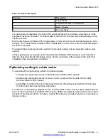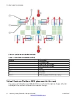
Table 16: Data center layout
Diagram
Description
1
Chassis racks
2
Cold aisle floor tiles in a raised floor
3
Back of chassis
4
Front of chassis
In a data center configuration, the front of the equipment faces the cold aisle, while the rear of the
equipment faces the hot aisle. The chassis take in cold air from the cold aisle and discharge hot air
into the hot aisle.
Each Virtual Services Platform 9012 chassis takes in cold air from the left and discharges hot air to
the right. The Virtual Services Platform 9010 chassis takes in cold air from the front and discharges
hot air from the back.
The typical data center layout works well for front-to-back cooling, but not as well for side-to-side
cooling.
In this typical setup, if you place each Virtual Services Platform 9012 chassis in a row from left to
right, the chassis to the left discharges hot air into the cool intake of the chassis to the right. This
installation does not optimize cool airflow.
Optimizing cooling in a data center
To optimize left-to-right cooling, perform the following tasks:
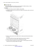
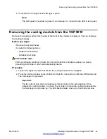
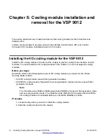
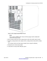
• Increase the space between each Virtual Services Platform 9012 chassis
• Relocate the cooling floor tiles to improve cool air movement into the side of the Virtual
Services Platform 9012 chassis
• Add baffles to redirect the hot air discharged from the Virtual Services Platform 9012 chassis
from the right side to the hot aisle at the back
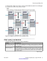
For instance, in the following diagram the hot and cold aisles remain, but now space exists between
some of the Virtual Services Platform 9012 chassis. Baffles are added to redirect air from the side to
the back of the chassis into the hot aisles. Cooling floor tiles are relocated near the cool air intake to
improve cooling.
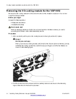
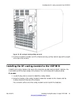
Virtual Services Platform 9012
March 2015
Installing Cooling Modules in Avaya VSP 9000
41


