background image

Avaya 9130 EBM Site Preparation, Installation and Operator’s Manual

S

164201770 Rev 1

15

Chapter 2

Installation

NOTE

If you are installing the UPS and the Extended Battery Module (EBM) together,

follow the installation instructions in the UPS user’s guide.

NOTE

EBMs can be installed easily without turning the UPS off or disconnecting the load.

If you prefer to remove input power to install an EBM, refer to “UPS Shutdown” in the UPS
user’s guide.

This section explains:

S

Equipment inspection

S

Unpacking the cabinet

S

Checking the accessory kit

S

EBM installation

Inspecting the Equipment

If any equipment has been damaged during shipment, keep the shipping
cartons and packing materials for the carrier or place of purchase and file
a claim for shipping damage. If you discover damage after acceptance,
file a claim for concealed damage.

NOTE

Check the battery recharge date on the shipping carton label. If the date has passed

and the batteries were never recharged, do not use the UPS. Contact your Avaya service
representative.

Summary of Contents for 9130 EBM

Page 1: ...Avaya 9130 Extended Battery Module EBM Site Preparation Installation and Operator s Manual www powerware com avaya...

Page 2: ...r more information contact your local recycling reuse or hazardous waste center This symbol indicates that you should not discard waste electrical or electronic equipment WEEE in the trash For proper...

Page 3: ...essories 17 Tools Required 17 Rackmount Setup 18 Rackmount Wiring Installation 21 3 Operation 27 Configuring the UPS for EBMs 27 Running Battery Tests 28 Configuring Automatic Restart 29 4 Maintenance...

Page 4: ...TABLE OF CONTENTS Avaya 9130 EBM Site Preparation Installation and Operator s Manual S 164201770 Rev 1 ii...

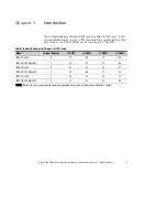
Page 5: ...see Table 1 Up to four EBMs can be installed with the UPS Table 1 Battery Runtimes in Minutes at 100 Load Model Internal Batteries 1 EBM 2 EBMs 3 EBMs 4 EBMs 1000 VA 120V 5 30 55 83 108 1000 VA 208 23...

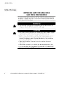
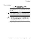
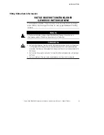
Page 6: ...k of electric shock Battery circuit is not isolated from AC input Hazardous voltages might exist between battery terminals and ground Test before touching S Batteries can present a risk of electrical...

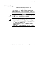
Page 7: ...gikilde batterier Udgangsstikkene kan endog v re str mf rende n r UPS en ikke er koblet til en vekselstr msforsyning ADVARSEL S Batterierne kan give risiko for elektrisk st d eller brands r for rsaget...

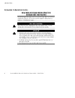
Page 8: ...erijen De uitgangscontactdoos kan onder spanning staan zelfs wanneer de UPS niet is aangesloten op de netspanning OPGELET S Batterijen leveren gevaar op voor elektrische schokken en kunnen brandwonden...

Page 9: ...ss UPS virtal hteess on oma energianl hde akut L ht vastakkeissa voi olla j nnite vaikka UPS virtal hdett ei ole kytketty verkkovirtaan VARO S Akut voivat aiheuttaa s hk iskun tai palovammojen vaaran...

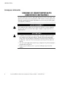
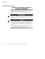
Page 10: ...source d alimentation batteries Il est possible que les prises de sortie soient sous tension m me lorsque l onduleur n est pas connect e une alimentation CA ATTENTION S Les batteries peuvent pr sente...

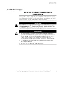
Page 11: ...elle Batterien Die Ausgangssteckdosen k nnen Spannung f hren auch wenn das UPS USV nicht an eine Wechselstromquelle angeschlossen ist VORSICHT S Batterien k nnen das Risiko eines elektrischen Schlags...

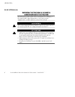
Page 12: ...batterie Le prese d uscita possono essere sotto tensione anche quando l UPS non collegato all alimentazione elettrica CA ATTENZIONE S Le batterie possono comportare un rischio di scossa elettrica o d...

Page 13: ...lder sin egen energikilde batterier Utgangsstikkene kan v re str mf rende selv n r UPS enheten ikke er koblet til et str muttak FORSIKTIG S Batterier kan utgj re en fare for elektrisk st t eller brann...

Page 14: ...ergia baterias As tomadas de sa da podem estar energizadas mesmo que o no break n o esteja conectado a uma fonte de energia el trica PERIGO S As baterias podem oferecer risco de choque el trico ou que...

Page 15: ...INTRODUCTION Avaya 9130 EBM Site Preparation Installation and Operator s Manual S 164201770 Rev 1 11 S S S...

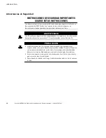
Page 16: ...ater as Los recept culos de salida pueden transportar voltaje activo aun cuando el SIE no est conectado con una fuente de CA PRECAUCI N S Las bater as pueden constituir un riesgo de descarga el ctrica...

Page 17: ...VARNING Den h r UPS enheten inneh ller sin egen energik lla batterier Uttagen kan vara sp nningsf rande ven d UPS enheten inte r ansluten till sp nningsn tet VIKTIGT S Batterierna kan inneb ra en ris...

Page 18: ...INTRODUCTION Avaya 9130 EBM Site Preparation Installation and Operator s Manual S 164201770 Rev 1 14...

Page 19: ...hutdown in the UPS user s guide This section explains S Equipment inspection S Unpacking the cabinet S Checking the accessory kit S EBM installation Inspecting the Equipment If any equipment has been...

Page 20: ...t Use care when moving and opening the carton Leave the components packaged until ready to install To unpack the cabinet and accessories 1 Open the outer carton and remove the accessories packaged wit...

Page 21: ...6 cm 24 to 30 inches deep Checking the Rail Kit Accessories Verify that the following rail kit items are included for each cabinet S Left rail assembly Left rail Rear rail 3 M4 8 pan head screws S Rig...

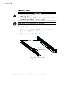
Page 22: ...ectly below the UPS so that all wiring between the cabinets is installed behind the front covers and is inaccessible to users NOTE Mounting rails are required for each individual cabinet To install th...

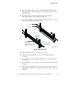
Page 23: ...to the rear of the rack M6 16 Pan Head Screws 6 places Front of Rack M6 Cage Nuts 6 places Tighten adjustment screws after rail attachment 3 places each rail Position 4 Position 1 Figure 2 Securing t...

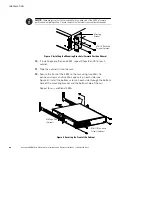
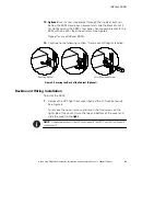
Page 24: ...talling the Mounting Brackets Forward Position Shown 10 If installing more than one EBM repeat Steps 8 and 9 for each cabinet 11 Slide the cabinet s into the rack 12 Secure the front of the EBM to the...

Page 25: ...r any additional EBMs 14 Continue to the following section Rackmount Wiring Installation Rear Stop Bracket M3 8 Pan Head Screw Figure 5 Securing the Back of the Cabinet Optional Rackmount Wiring Insta...

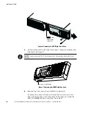
Page 26: ...emove the EBM cable knockout see Figure 7 NOTE Use care to protect the LCD control panel and the connected ribbon cable from damage esc Knockout for EBM Cable Figure 7 Removing the EBM Cable Knockout...

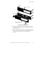
Page 27: ...ure 8 Removing the EBM Front Cover 4 For the bottom or only EBM remove the EBM cable knockout on the top of the EBM front cover See Figure 8 for the location of the top EBM cable knockout 5 If you are...

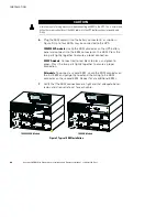
Page 28: ...nector on the UPS battery panel and connect it to the EBM connector on the EBM Press the two parts tightly together to ensure a proper connection 3000 VA models Connect red to red black to black and g...

Page 29: ...it connects with the cover hook near the left side of the EBM cabinet Reinstall the two screws on the right side of the front cover See Figure 8 on page 23 Repeat for each additional EBM 9 Verify tha...

Page 30: ...INSTALLATION Avaya 9130 EBM Site Preparation Installation and Operator s Manual S 164201770 Rev 1 26...

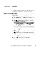
Page 31: ...activate the menu options then select SETTINGS USER SETTINGS and NUMBER OF BATTERY STRINGS 2 Use the or buttons to select the number of battery strings according to your UPS configuration All UPS and...

Page 32: ...S The UPS must be in Normal mode with no active alarms S The bypass voltage must be acceptable To run a manual battery test 1 Press any button to activate the menu options 2 Select CONTROL then START...

Page 33: ...or if another battery test is initiated and passed Configuring Automatic Restart The UPS automatically restarts if utility returns after the output was shut off due to exhausted batteries a shutdown...

Page 34: ...OPERATION Avaya 9130 EBM Site Preparation Installation and Operator s Manual S 164201770 Rev 1 30...

Page 35: ...tery connector refer to the UPS manual NOTE The batteries in the UPS are rated for a 3 5 year service life The length of service life varies depending on the frequency of usage and ambient temperature...

Page 36: ...ing batteries WARNING S Servicing should be performed by qualified service personnel knowledgeable of batteries and required precautions Keep unauthorized personnel away from batteries S Batteries can...

Page 37: ...ttery can result in electrical shock The likelihood of such shock can be reduced if such grounds are removed during installation and maintenance applicable to equipment and remote battery supplies not...

Page 38: ...s a minimum of two people To replace the EBMs 1 Remove the front cover of each EBM see Figure 10 To remove the cover remove and retain the two screws on the right side of the cover Grasp the sides of...

Page 39: ...n of the top EBM cable knockout 7 If you are installing more than one new EBM for each additional EBM remove the EBM cable knockout on the top and bottom of the EBM front cover See Figure 10 for the l...

Page 40: ...additional EBM 11 Verify that all wiring connecting the UPS and EBM s is installed behind the front covers and is inaccessible to users Testing New Batteries To test new batteries 1 Plug the UPS into...

Page 41: ...quired Refer to your local codes for disposal requirements S Do not open or mutilate the battery or batteries Released electrolyte is harmful to the skin and eyes It may be toxic CAUTION Do not discar...

Page 42: ...MAINTENANCE Avaya 9130 EBM Site Preparation Installation and Operator s Manual S 164201770 Rev 1 38...

Page 43: ...ns S Battery Table 2 Extended Battery Module EBM Model List EBM Model Battery Voltage For Power Ratings 1000 VA 36 Vdc 1000 VA 1500 VA 48 Vdc 1500 VA 3000 VA 72 Vdc 3000 VA Table 3 Weights and Dimensi...

Page 44: ...Ah 1500 VA models 48 Vdc 2x4 12V 9 Ah 3000 VA models 72 Vdc 2x6 12V 9 Ah Fuses Not applicable 4 30A 125 Vdc fuses per EBM Type Sealed maintenance free valve regulated lead acid with minimum 3 year flo...

Page 45: ...rsion number if available S Date of failure or problem S Symptoms of failure or problem S Customer return address and contact information Parts List SAP Code Description 790341054021 1000 VA 120V UPS...

Page 46: ...SERVICE AND SUPPORT Avaya 9130 EBM Site Preparation Installation and Operator s Manual S 164201770 Rev 1 42...

Page 47: ......

Page 48: ...1642017701 164201770 1...

Reviews: