background image

UPS MAINTENANCE

Avaya 9130 1000–3000 VA UPS Site Preparation, Installation and Operator’s Manual

S

164201765 Rev 1

61

S

Determine if the battery is inadvertently grounded. If inadvertently grounded, remove
source from ground. Contact with any part of a grounded battery can result in electrical
shock. The likelihood of such shock can be reduced if such grounds are removed during
installation and maintenance (applicable to equipment and remote battery supplies not
having a grounded supply circuit).

S

ELECTRIC ENERGY HAZARD. Do not attempt to alter any battery wiring or connectors.
Attempting to alter wiring can cause injury.

S

Disconnect charging source prior to connecting or disconnecting battery terminals.

Replacing UPS Internal Batteries

C A U T I O N

The UPS internal batteries are heavy (see page 70). Use caution when handling the heavy
batteries.

The internal batteries are located behind the UPS right front cover
(behind the LCD control panel). The internal batteries are packaged
together as one unit for easier handling.

To replace the batteries in the UPS:

1.

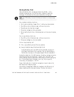
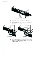
Remove the UPS right front cover (see Figure 19).

To remove the cover, remove and retain the two screws on the
right side of the cover. Grasp the top and bottom of the cover and
slide the cover to the

right

.

NOTE

A ribbon cable connects the LCD control panel to the UPS. Do not pull on the cable

or disconnect it.

Summary of Contents for 9130

Page 1: ...Avaya 9130 1000 3000 VA Uninterruptible Power Systems Site Preparation Installation and Operator s Manual www powerware com avaya ...

Page 2: ......

Page 3: ...Avaya 9130 1000 3000 VA Uninterruptible Power Systems Site Preparation Installation and Operator s Manual www powerware com avaya ...

Page 4: ...ppareil numérique de classe A respecte toutes les exigences du Règlement sur le matériel brouilleur du Canada ICES 003 EN 62040 2 Some configurations are classified under EN 62040 2 as Class A UPS for Unrestricted Sales Distribution For these configurations the following applies WARNING This is a Class A UPS Product In a domestic environment this product may cause radio interference in which case ...

Page 5: ...icular installation If this equipment does cause harmful interference to radio or television reception which can be determined by turning the equipment off and on the user is encouraged to try to correct the interference by one or more of the following measures S Reorient or relocate the receiving antenna S Increase the separation between the equipment and the receiver S Connect the equipment into...

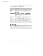
Page 6: ... Phone 358 9 452 661 Fax 358 9 452 665 68 Special Symbols The following are examples of symbols used on the UPS or accessories to alert you to important information RISK OF ELECTRIC SHOCK Observe the warning associated with the risk of electric shock symbol CAUTION REFER TO OPERATOR S MANUAL Refer to your operator s manual for additional information such as important operating and maintenance inst...

Page 7: ...nt Setup 20 Wiring Installation 23 Installing the UPS 23 Connecting the EBM s 26 UPS Initial Startup 29 4 Operation 33 Control Panel Functions 33 Changing the Language 34 Display Functions 34 User Settings 36 Operating Modes 39 Normal Mode 39 Battery Mode 39 Bypass Mode 40 Standby Mode 40 UPS Startup and Shutdown 41 Starting the UPS 41 Starting the UPS on Battery 42 UPS Shutdown 42 Transferring th...

Page 8: ... Card 52 Remote Emergency Power off 53 Relay Output Contacts 54 Programmable Signal Inputs 55 Modem Operation 57 Powerware LanSafe Power Management Software 57 6 UPS Maintenance 59 UPS and Battery Care 59 Storing the UPS and Batteries 59 When to Replace Batteries 60 Replacing Batteries 60 Replacing UPS Internal Batteries 61 Replacing EBMs 64 Testing New Batteries 66 Recycling the Used Battery or U...

Page 9: ...lude S True online double conversion technology with high power density utility frequency independence and generator compatibility S Rackmount models in a space optimizing 2U size that fits any standard 48 cm 19 rack S ABM technology that uses advanced battery management to increase battery service life optimize recharge time and provide a warning before the end of useful battery life S Selectable...

Page 10: ... 9130 1000 3000 VA UPS Site Preparation Installation and Operator s Manual S 164201765 Rev 1 2 Figure 1 shows the Avaya 9130 UPS and Figure 2 shows the optional EBM Figure 1 The Avaya 9130 UPS Figure 2 The Avaya 9130 EBM ...

Page 11: ...environment free of conductive contaminants Ambient temperature must not exceed 40 C 104 F Do not operate near water or excessive humidity 90 maximum S To reduce the risk of fire connect only to a circuit provided with branch circuit overcurrent protection in accordance with the National Electrical Code NEC ANSI NFPA 70 S Output overcurrent protection and disconnect switch must be provided by othe...

Page 12: ...der LIVSFARLIG HØJSPÆNDING Alle reparationer og vedligeholdelse bør kun udføres af en AUTORISERET SERVICETEKNIKER Ingen af UPS ens indvendige dele kan repareres af brugeren ADVARSEL S Denne UPS indeholder sin egen energikilde batterier Udgangsstikket på UPS en kan endog være strømførende når UPS en ikke er koblet til en vekselstrømsforsyning S Installér denne UPS i et temperatur og fugtighedskontr...

Page 13: ...tructies voordat u de apparatuur in bedrijf neemt en bewaar deze handleiding als naslagwerk GEVAAR Deze UPS bevat LEVENSGEVAARLIJKE ELEKTRISCHE SPANNING Alle reparaties en onderhoud dienen UITSLUITEND DOOR ERKEND SERVICEPERSONEEL te worden uitgevoerd Er bevinden zich GEEN ONDERDELEN in de UPS die DOOR DE GEBRUIKER kunnen worden GEREPAREERD WAARSCHUWING S Deze UPS bevat een eigen energiebron accu s...

Page 14: ...rden opgeruimd Raadpleeg hiervoor uw plaatselijke voorschriften S Nooit batterijen in het vuur gooien De batterijen kunnen ontploffen Tarkeita Turvaohjeita TÄRKEITÄ TURVAOHJEITA SUOMI SÄILYTÄ NÄMÄ OHJEET Tämä käyttöohje sisältää tärkeitä ohjeita joita on noudatettava UPS virtalähteen ja akkujen asennuksen ja huollon yhteydessä Lue kaikki ohjeet ennen laitteiston käyttöä ja säilytä ohje myöhempää t...

Page 15: ...SIGNES DE SÉCURITÉ IMPORTANTES CONSERVER CES INSTRUCTIONS Ce manuel comporte des instructions importantes que vous êtes invité à suivre lors de toute procédure d installation et de maintenance des batteries et de l onduleur Veuillez consulter entièrement ces instructions avant de faire fonctionner l équipement et conserver ce manuel afin de pouvoir vous y reporter ultérieurement DANGER Cet onduleu...

Page 16: ... les précautions appropriées L entretien doit être réalisé par du personnel qualifié connaissant bien les batteries et les précautions nécessaires N autorisez aucun personnel non qualifié à manipuler les batteries S Une mise au rebut réglementaire des batteries est obligatoire Consulter les règlements en vigueur dans votre localité S Ne jamais jeter les batteries au feu L exposition aux flammes ri...

Page 17: ...tellern geliefert werden S Um internationale Normen und Verdrahtungsvorschriften zu erfüllen dürfen die an den Ausgang dieser USV angeschlossenen Geräte zusammen einen Erdableitstrom von insgesamt 3 5 Milliampere nicht überschreiten VORSICHT S Batterien können das Risiko eines elektrischen Schlags bergen oder durch hohen Kurzschlussstrom in Brand geraten Die richtigen Vorsichtsmaßnahmen beachten D...

Page 18: ...hio di incendio effettuare il collegamento soltanto a un circuito dotato di una protezione da sovraccarico per il circuito derivato di max 100 ampere come stabilito dalle norme statunitensi sugli impianti elettrici NEC ANSI NFPA 70 S La protezione da sovraccarico per le uscite e l interruttore di scollegamento devono essere forniti da altri produttori S Per conformità con gli standard internaziona...

Page 19: ...tighet som er fritt for ledende forurensende stoffer Romtemperaturen må ikke overskride 40 C Den må ikke brukes i nærheten av vann eller ved meget høy luftfuktighet 90 maks S For å redusere brannfaren skal det bare kobles til et kretsløp med 100 A maksimum linjeforgrenings overbelastningsbeskyttelse i henhold til NEC ANSI NFPA 70 S Overbelastningsbeskyttelse for strømutgang og bryterkontakt skal l...

Page 20: ...e contaminadores condutíveis A temperatura ambiente não deve exceder 40 C Não opere próximo a água ou em umidade excessiva máx 90 S Para reduzir o risco de incêndio conecte somente ao circuito fornecido com a proteção máxima de 100 ampères contra a sobretensão do circuito derivado de acordo com a norma ANSI NFPA 70 do NEC S A proteção contra a sobretensão de saída e o disjuntor deve ser fornecida ...

Page 21: ...если он не подключен к сети переменного тока S Для снижения опасности пожара или поражения электрическим током устанавливайте ИБП в закрытом помещении с контролируемыми температурой и влажностью в котором отсутствуют проводящие загрязняющие вещества Температура окружающего воздуха не должна превышать 40 С Не эксплуатируйте устройство около воды или в местах с повышенной влажностью макс 90 S Для то...

Page 22: ...nimiento del SIE y de las baterías Por favor lea todas las instrucciones antes de poner en funcionamiento el equipo y guarde este manual para referencia en el futuro PELIGRO Este SIE contiene VOLTAJES MORTALES Todas las reparaciones y el servicio técnico deben ser efectuados SOLAMENTE POR PERSONAL DE SERVICIO TÉCNICO AUTORIZADO No hay NINGUNA PARTE QUE EL USUARIO PUEDA REPARAR dentro del SIE ADVER...

Page 23: ...uisitos pertinentes S Nunca deseche las baterías en el fuego Las baterías pueden explotar si se las expone a la llama Säkerhetsföreskrifter VIKTIGA SÄKERHETSFÖRESKRIFTER SPARA DESSA FÖRESKRIFTER Den här anvisningen innehåller viktiga instruktioner som du ska följa under installation och underhåll av UPS enheten och batterierna Läs alla instruktioner innan du använder utrustningen och spara den här...

Page 24: ...nationell standard och installationsföreskrifter får inte den totala utrustning som anslutits till uttagen på denna UPS enhet ha läcksström som överstiger 3 5 milliampere VIKTIGT S Batterierna kan innebära en risk för elektrisk stöt eller brännskada från kortsluten starkström Iakttag lämpliga försiktighetsåtgärder Service ska utföras av utbildad servicepersonal med kunskap om batterierna och nödvä...

Page 25: ...itial startup Inspecting the Equipment If any equipment has been damaged during shipment keep the shipping cartons and packing materials for the carrier or place of purchase and file a claim for shipping damage If you discover damage after acceptance file a claim for concealed damage NOTE Check the battery recharge date on the shipping carton label If the date has passed and the batteries were nev...

Page 26: ...e accessories packaged with the cabinet 2 Carefully lift the cabinet out of the outer carton 3 Discard or recycle the packaging in a responsible manner or store it for future use Place the cabinet in a protected area that has adequate airflow and is free of humidity flammable gas and corrosion Checking the Accessory Kit Verify that the following additional items are included with the UPS S UPS use...

Page 27: ...rom 61 to 76 cm 24 to 30 inches deep Checking the Rail Kit Accessories Verify that the following rail kit items are included for each cabinet S Left rail assembly Left rail Rear rail 3 M4 8 pan head screws S Right rail assembly Right rail Rear rail 3 M4 8 pan head screws S Rail hardware kit 10 M6 16 pan head screws 10 M6 cage nuts 2 rear stop brackets 2 M3 8 pan head screws S Mounting bracket kit ...

Page 28: ... install the EBM s directly below the UPS so that all wiring between the cabinets is installed behind the front covers and is inaccessible to users NOTE Mounting rails are required for each individual cabinet To install the rail kit 1 Assemble the left and right rails to the rear rails as shown in Figure 3 Do not tighten the screws Adjust each rail size for the depth of your rack Rear Rails Right ...

Page 29: ...ssembly to the rear of the rack M6 16 Pan Head Screws 6 places Front of Rack M6 Cage Nuts 6 places Tighten adjustment screws after rail attachment 3 places each rail Position 4 Position 1 Figure 4 Securing the Rails 5 Repeat Steps 3 and 4 for the other rail assembly 6 Tighten the three adjustment screws in the middle of each rail assembly 7 If installing optional cabinets repeat Step 1 through Ste...

Page 30: ...ing the Mounting Brackets Forward Position Shown 10 If installing optional cabinets repeat Steps 8 and 9 for each cabinet 11 Slide the UPS and any optional cabinets into the rack 12 Secure the front of the UPS to the rack using two M6 16 pan head screws and two M6 cage nuts on each side see Figure 6 Install the bottom screw on each side through the bottom hole of the mounting bracket and the botto...

Page 31: ...an Head Screw Figure 7 Securing the Back of the Cabinet Optional Wiring Installation This section explains S Installing the UPS including connecting the UPS internal batteries S Connecting any optional EBMs Installing the UPS NOTE Do not make unauthorized changes to the UPS otherwise damage may occur to your equipment and void your warranty NOTE Do not connect the UPS power cord to utility until a...

Page 32: ...rmal and will not harm personnel Connect the cables quickly and firmly 2 Connect the internal battery connector see Figure 9 1000 1500 VA models Unclip the top rightmost white connector from the battery panel and move it to the left to connect to the white connector at the top left Connect red to red and black to black Press the two parts tightly together to ensure a proper connection Clip the wir...

Page 33: ...ble is routed through the knockout on the bottom of the cover Slide the cover to the left until it aligns with the left front cover Reinstall the two screws on the right side of the right front cover 5 If your rack has conductors for grounding or bonding of ungrounded metal parts connect the ground cable not supplied to the ground bonding screw See Rear Panels on page 76 for the location of the gr...

Page 34: ...ve the EBM cable knockout see Figure 10 NOTE Use care to protect the LCD control panel and the connected ribbon cable from damage esc Knockout for EBM Cable Figure 10 Removing the EBM Cable Knockout 2 Remove the front cover of each EBM see Figure 11 To remove the cover remove and retain the two screws on the right side of the cover Grasp the sides of the cover and slide the cover to the left and t...

Page 35: ...ok Figure 11 Removing the EBM Front Cover 3 For the bottom or only EBM remove the EBM cable knockout on the top of the EBM front cover See Figure 11 for the location of the top EBM cable knockout 4 If you are installing more than one EBM for each additional EBM remove the EBM cable knockout on the top and bottom of the EBM front cover See Figure 11 for the location of the EBM cable knockouts ...

Page 36: ... EBM connector on the UPS battery panel and connect it to the EBM connector on the EBM Press the two parts tightly together to ensure a proper connection 3000 VA models Connect red to red black to black and green to green Press the two parts tightly together to ensure a proper connection All models To connect a second EBM unclip the EBM connector on the first EBM and pull gently to extend the wiri...

Page 37: ...he UPS NOTE Verify that the total equipment ratings do not exceed the UPS capacity to prevent an overload alarm 1 Verify that the internal batteries are connected See Installing the UPS on page 23 2 If optional EBMs are installed verify that the EBMs are connected to the UPS See Connecting the EBM s on page 26 3 Plug the equipment to be protected into the UPS but do not turn on the protected equip...

Page 38: ...n page 46 to set the number of installed EBMs 13 To change any other factory set defaults see Operation on page 33 NOTE Avaya recommends setting the date and time NOTE At initial startup the UPS sets system frequency according to input line frequency input frequency auto sensing is enabled by default After initial startup auto sensing is disabled until manually re enabled by output frequency setti...

Page 39: ...charge for 48 hours after installation or long term storage If optional EBMs are installed see the recharge times listed in Table 19 on page 75 15 Keep your UPS firmware updated See Updating the UPS Firmware on page 67 16 If you are installing power management software refer to the ConnectUPS Web SNMP Card Quick Start Instructions and ConnectUPS Web SNMP Card User s Guide on the Software Suite CD ...

Page 40: ...INSTALLATION Avaya 9130 1000 3000 VA UPS Site Preparation Installation and Operator s Manual S 164201765 Rev 1 32 ...

Page 41: ...rategy and configuring bypass settings load segments and battery settings Control Panel Functions The UPS has a four button graphical LCD with backlight It provides useful information about the UPS itself load status events measurements and settings see Figure 13 Power On Indicator green On Battery Indicator yellow Bypass Indicator yellow Alarm Indicator red On Off Button Escape Up Down Enter esc ...

Page 42: ...ion Red On The UPS has an active alarm or fault See Troubleshooting on page 79 for additional information Changing the Language Press and hold the first button on the left for approximately three seconds to select the language menu This action is possible from any LCD menu screen Display Functions As the default or after 15 minutes of inactivity the LCD displays the start screen The backlit LCD au...

Page 43: ...Hz Input V Hz Bypass V Hz Input Line Events Battery V min Control Go to Bypass Transfers the UPS system to internal Bypass mode When this command is active the option changes to Go to Normal Start Battery Test Starts a manual battery test See Running Battery Tests on page 47 Reset Error State Clears a Battery Test Failed alarm Load Segments Load segment 1 ON OFF Load segment 2 ON OFF These command...

Page 44: ...tup Not Used Force Bypass Remote Shutdown Delayed Shutdown On Generator Building Alarm 1 Active High Low See Programmable Signal Inputs on page 55 RS232 3 Not Used High cXSlot Serial Delayed Shutdown High cXSlot Signal Remote Shutdown Low Relay Configuration UPS ok On Bypass On Battery Battery Low Ext Charger On See Relay Output Contacts on page 54 Standard UPS ok RS232 1 Battery Low RS232 8 On Ba...

Page 45: ...ments on page 45 Load Segment 1 No Delay Load Segment 2 No Delay Automatic on Battery Shutdown Disabled No Delay 1s 2s 32767s Shutdown cancels if utility returns before the delay expires See Configuring Load Segments on page 45 Load Segment 1 Disabled Load Segment 2 Disabled Start on Battery NOTE Utility must be present and output enabled at initial UPS startup Enabled Disabled After initial start...

Page 46: ... for EBMs on page 46 1 Battery Charge Mode ABM Cycling Constant ABM Cycling Temperature Compensated Charging Enabled Disabled If Disabled the default charger voltages for 25 C 77 F are assumed Enabled Battery Charge to Restart Not Checked 10 20 100 If a percentage is selected automatic restart if enabled occurs when the battery s charge reaches the selected level Not Checked Battery Low Alarm Imme...

Page 47: ...eturning to its previous mode Optional High Efficiency and Energy Saving settings minimize heat contribution to the rack environment See User Settings on page 36 Battery Mode When the UPS is operating during a power outage the alarm beeps once every five seconds and the indicator illuminates solid When the utility power returns the UPS transfers to Normal mode operation while the battery recharges...

Page 48: ... S The UPS has an overtemperature condition S The UPS has an overload condition listed in Table 15 on page 72 NOTE The UPS shuts down after a specified delay for overload conditions listed in Table 15 on page 72 The UPS remains on to alarm the fault Standby Mode When the UPS is turned off and remains plugged into a power outlet the UPS is in Standby mode The indicator is off indicating that power ...

Page 49: ...t the UPS transfers to Standby mode UPS on standby 4 Press the button on the UPS front panel for at least one second The UPS front panel display changes status to UPS starting 5 Check the UPS front panel display for active alarms or notices Resolve any active alarms before continuing See Troubleshooting on page 79 If the indicator is on do not proceed until all alarms are clear Check the UPS statu...

Page 50: ...PS supplies power to your equipment 2 Check the UPS front panel display for active alarms or notices besides the UPS on Battery notice and notices that indicate missing utility power Resolve any active alarms before continuing See Troubleshooting on page 79 Check the UPS status from the front panel to view the active alarms Correct the alarms and restart if necessary 3 Press the ESC button until t...

Page 51: ...ces ESC L ASCII characters 27 and 76 or ESC I ASCII characters 27 and 108 The UPS returns a header containing the UPS identification UPS type part number and serial number firmware version and the current date and time followed by the event history 2 Use the connected communication device to view or print the information The report is delivered in ASCII format Setting Power Strategy On the High Ef...

Page 52: ...e Qualify Bypass setting Qualify Bypass The default allows a transfer to Bypass only when Bypass is within the following specifications S Bypass voltage is between the Bypass Voltage Low Limit and Bypass Voltage High Limit settings S Bypass frequency is within nominal frequency 5 Hz S The inverter is synchronized with Bypass when the Unsynchronized Transfers setting is disabled You can prohibit By...

Page 53: ...software see your power management software manual for details refer to the Software Suite CD or www powerware com avaya for the latest information To control the load segments through the display 1 Press any button to activate the menu options then select CONTROL and LOAD SEGMENTS 2 Set the desired load segment ON or OFF and ENTER to confirm 3 Set the other load segment if applicable To set the r...

Page 54: ...nel display to activate the menu options then select SETTINGS USER SETTINGS and NUMBER OF BATTERY STRINGS 2 Use the or buttons to select the number of battery strings according to your UPS configuration All UPS and EBM Cabinets Number of Battery Strings UPS only internal batteries 1 default UPS 1 EBM 3 UPS 2 EBMs 5 UPS 3 EBMs 7 UPS 4 EBMs 9 NOTE If 0 is selected no batteries are connected and all ...

Page 55: ... to run S The UPS must be in Normal mode with no active alarms S The bypass voltage must be acceptable To run a manual battery test 1 Press any button to activate the menu options 2 Select CONTROL then START BATTERY TEST During the battery test the UPS transfers to Battery mode and discharges the batteries for 25 seconds The front panel displays Battery test running and the percentage of the test ...

Page 56: ...detected or if another battery test is initiated and passed Configuring Automatic Restart The UPS automatically restarts if utility returns after the output was shut off due to exhausted batteries a shutdown input signal or automatic shutdown command You can set the load segment for the amount of time to delay the restart once utility returns using the Automatic Start Delay setting You can also co...

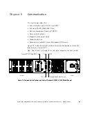
Page 57: ...REPO S Relay output contacts S Programmable signal inputs S Modem operation S Powerware LanSafe Power Management Software Figure 14 shows the location of the communication options and control terminals on a typical UPS See Rear Panels on page 76 for rear panel diagrams for each model ConnectUPS BD Web SNMP Card USB REPO RS 232 Standard Relay Output Contact Output Input Figure 14 Communication Opti...

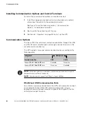
Page 58: ...lities through the USB and RS 232 communication ports or through a connectivity card in the available communication bay The UPS supports two serial communication devices according to the following table Independent Multiplexed Communication Bay USB RS 232 ConnectUPS BD Web SNMP Card Available Not in use ConnectUPS BD Web SNMP Card Not in use Available NOTE You can configure relays signal inputs an...

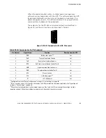
Page 59: ...232 Communication Port Pin Assignment Pin Number Signal Name Function Direction from the UPS 1 DCD Battery Low signal1 3 Out 2 RxD Transmit to external device Out 3 TxD Receive from external device2 In 4 DTR PnP from external device tied to Pin 6 In 5 GND Signal common tied to chassis 6 DSR To external device tied to Pin 4 Out 7 RTS No connection In 8 CTS On Battery signal1 3 Out 9 RI 8 12 Vdc pow...

Page 60: ... monitor the UPS several different ways S Using a Web browser such as MicrosoftR Internet Explorer to monitor and manage the connected UPS S Using your Internet ready cell phone or PDA personal digital assistant S Using SNMP compatible network management software user supplied that monitors the UPS in a method similar to that of other network devices Refer to the ConnectUPS Web SNMP Card User s Gu...

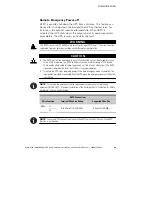
Page 61: ...d circuits Reinforced insulation to the utility is required The REPO switch must have a minimum rating of 24 Vdc and 20 mA and be a dedicated latching type switch not tied into any other circuit The REPO signal must remain active for at least 250 ms for proper operation S To ensure the UPS stops supplying power to the load during any mode of operation the input power must be disconnected from the ...

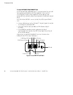
Page 62: ...the UPS reconnect re open the REPO connector pins and turn on the UPS manually Maximum resistance in the shorted loop is 10 ohm NOTE Always test the REPO function before applying your critical load to avoid accidental load loss Relay Output Contacts The UPS incorporates three programmable relay outputs with potential free contacts for remote alarm indications a standard relay port and two outputs ...

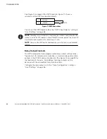
Page 63: ...ypass Activated when the UPS is NOT on bypass operation On Battery Activated when the UPS operates on battery and the On Battery Notice Delay time has expired Battery Low Activated with the Battery Low alarm according to the Battery Low Alarm setting Ext Charger On Controls an optional external battery charger on and off Figure 18 shows a schematic of the relay output contacts Common Normally Clos...

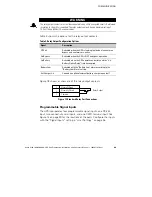
Page 64: ...efined remote shutdown delay The batteries continue charging Inactive input does not abort the shutdown countdown and does not cause the UPS to start up automatically Delayed Shutdown and restart If active the UPS output turns off after a user defined delayed shutdown delay The batteries continue charging Inactive input does not abort the shutdown countdown but will cause the UPS to start up autom...

Page 65: ...werware LanSafe software select serial port installation For the UPS manufacturer and model select Powerware and Powerware 9130 If the Powerware brand options are not available in your version of the software select Generic UPSs for the manufacturer and Generic XCP for the model Powerware LanSafe software provides up to date graphics of UPS power and system data and power flow It also gives you a ...

Page 66: ...COMMUNICATION Avaya 9130 1000 3000 VA UPS Site Preparation Installation and Operator s Manual S 164201765 Rev 1 58 ...

Page 67: ...al battery connector see Figure 20 on page 62 NOTE The batteries in the UPS are rated for a 3 5 year service life The length of service life varies depending on the frequency of usage and ambient temperature Batteries used beyond expected service life will often have severely reduced runtimes Replace batteries at least every 5 years to keep units running at peak efficiency Storing the UPS and Batt...

Page 68: ...placing batteries WARNING S Servicing should be performed by qualified service personnel knowledgeable of batteries and required precautions Keep unauthorized personnel away from batteries S Batteries can present a risk of electrical shock or burn from high short circuit current Observe the following precautions 1 Remove watches rings or other metal objects 2 Use tools with insulated handles 3 Do ...

Page 69: ...tempting to alter wiring can cause injury S Disconnect charging source prior to connecting or disconnecting battery terminals Replacing UPS Internal Batteries CAUTION The UPS internal batteries are heavy see page 70 Use caution when handling the heavy batteries The internal batteries are located behind the UPS right front cover behind the LCD control panel The internal batteries are packaged toget...

Page 70: ...EBM cable is not connected to an EBM unclip the EBM cable and move it to the left out of the way See Figure 20 1000 1500 VA Models 3000 VA Models Internal Battery Connector Internal Battery Connector EBM Cable Battery Cover Plate Battery Cover Plate Figure 20 Disconnecting the UPS Internal Batteries Shown without EBMs 4 Grasp an edge of the battery cover plate and pull it forward gently Remove and...

Page 71: ...TION A small amount of arcing may occur when connecting the internal batteries This is normal and will not harm personnel Connect the cables quickly and firmly 8 Reconnect the internal battery connector Connect red to red and black to black Press the two parts tightly together to ensure a proper connection 9 1000 1500 VA models only If the EBM cable is not connected to an EBM clip the EBM cable ba...

Page 72: ...ck requires a minimum of two people To replace the EBMs 1 Remove the front cover of each EBM See Figure 21 To remove the cover remove and retain the two screws on the right side of the cover Grasp the sides of the cover and slide the cover to the left and then away from the cabinet Bottom EBM Cable Knockout underneath cover Top EBM Cable Knockout EBM Cover Hook Figure 21 Removing the EBM Front Cov...

Page 73: ...f the top EBM cable knockout 7 If you are installing more than one new EBM for each additional EBM remove the EBM cable knockout on the top and bottom of the EBM front cover See Figure 21 for the location of the EBM cable knockouts 8 Plug the new EBM s into the UPS For reference see Figure 12 on page 28 1000 1500 VA models Connect the EBM connector from the UPS to the EBM connector on the EBM Pres...

Page 74: ... Repeat for each additional EBM 11 Verify that all wiring connecting the UPS and EBM s is installed behind the front covers and is inaccessible to users Testing New Batteries To test new batteries 1 Plug the UPS into a power outlet for 48 hours to charge the batteries 2 Press any button to activate the menu options 3 Select CONTROL then START BATTERY TEST The UPS starts a battery test if the UPS i...

Page 75: ...es Released electrolyte is harmful to the skin and eyes It may be toxic CAUTION Do not discard the UPS or the UPS batteries in the trash This product contains sealed lead acid batteries and must be disposed of properly For more information contact your local recycling reuse or hazardous waste center CAUTION Do not discard waste electrical or electronic equipment WEEE in the trash For proper dispos...

Page 76: ...UPS MAINTENANCE Avaya 9130 1000 3000 VA UPS Site Preparation Installation and Operator s Manual S 164201765 Rev 1 68 ...

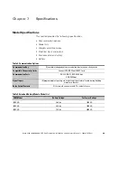
Page 77: ...ion Options Communication Bay 1 available independent communication bay for connectivity cards Compatible Connectivity Cards ConnectUPS BD Web SNMP Card Communication Ports RS 232 DB 9 1200 9600 bps USB 9600 bps Signal Inputs 4 programmable signal inputs signal and signal return for indicating building alarms or other use Relay Output Contacts 1 three pole connector with 1 contact closure Table 9 ...

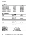
Page 78: ... 77 3000 VA 208 230 240V 790341054076 3000i 3000 VA 2700W Figure 27 on page 77 Table 11 Weights and Dimensions UPS Model Dimensions H W D Weight 1000 VA 86 5 438 430 mm 3 4 17 2 16 9 16 0 kg 35 3 lb 1500 VA 86 5 438 430 mm 3 4 17 2 16 9 19 5 kg 43 0 lb 3000 VA 86 5 438 600 mm 3 4 17 2 23 6 29 5 kg 65 0 lb EBM Model Dimensions H W D Weight 1000 VA 86 5 438 430 mm 3 4 17 2 16 9 22 1 kg 48 7 lb 1500 ...

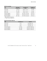
Page 79: ...0V 230V 4 3A 200 208 220 230 240 160 276 Vac 1500 VA 208 230 240V 230V 6 5A 200 208 220 230 240 160 276 Vac 3000 VA 208 230 240V 230V 13 0A 200 208 220 230 240 180 276 Vac 100V and 200V are derated by 20 110V and 208V are derated by 10 Table 14 Electrical Input Connections Model Input Connection Input Cable 1000 VA 120V 5 15P Attached line cord 1500 VA 120V 5 15P Attached line cord 3000 VA 120V L5...

Page 80: ...rter Output Overload Normal Mode 100 102 Activates Overload alarm Level 1 102 129 Load transfers to Bypass mode after 12 seconds Level 2 130 149 Load transfers to Bypass mode after 2 seconds Level 3 150 Load transfers to Bypass mode after 100 ms Level 4 NOTE Default configuration transfers immediately to Bypass at 102 Output Overload Bypass Mode 100 109 Activates Overload alarm Level 1 110 129 UPS...

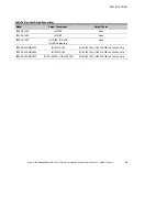
Page 81: ...ns Output Cables 1000 VA 120V 6 5 15R None 1500 VA 120V 6 5 15R None 3000 VA 120V 1 L5 30R 6 5 20R 2 20A AC breakers None 1000 VA 208 230 240V 6 IEC 320 10A 2 IEC IEC 10A 1 IEC 320 10A to Schuko 3 strip 1500 VA 208 230 240V 6 IEC 320 10A 2 IEC IEC 10A 1 IEC 320 10A to Schuko 3 strip 3000 VA 208 230 240V 8 IEC 320 10A 1 IEC 320 16A 2 IEC IEC 10A 1 IEC 320 16A to Schuko 3 strip ...

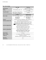
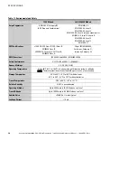
Page 82: ...s A CE per IEC EN 62040 2 Emissions Category C1 Immunity Category C2 EMC Emissions IEC 62040 2 ed2 2005 EN 62040 2 2006 Safety Conformance UL 1778 IEC 62040 1 1 IEC 60950 1 Agency Markings CE UL CUL NOM Operating Temperature 0 C to 40 C 32 F to 104 F in Online mode with linear derating for altitude NOTE Thermal protection switches load to Bypass in case of overheating Storage Temperature 20 C to 4...

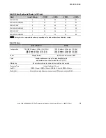
Page 83: ...tery charge Table 19 Battery Internal Batteries EBMs Configuration 700 1000 VA models 36 Vdc 3 12V 9 Ah 1500 VA models 48 Vdc 4 12V 9 Ah 3000 VA models 72 Vdc 6 12V 9 Ah 1000 VA models 36 Vdc 2x3 12V 9 Ah 1500 VA models 48 Vdc 2x4 12V 9 Ah 3000 VA models 72 Vdc 2x6 12V 9 Ah Fuses Not applicable 4 30A 125 Vdc fuses per EBM Type Sealed maintenance free valve regulated lead acid with minimum 3 year f...

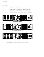
Page 84: ...ar panel Receptacles in Load Segment 1 are shaded Table 10 on page 70 lists the rackmount models Input and output components for each model are listed in Table 13 through Table 16 pages 71 through 73 For a description of communication features see Figure 14 on page 49 Figure 22 1000 VA 120V Model Figure 23 1000 VA 208 230 240V Models Figure 24 1500 VA 120V Model ...

Page 85: ...TIONS Avaya 9130 1000 3000 VA UPS Site Preparation Installation and Operator s Manual S 164201765 Rev 1 77 Figure 25 1500 VA 208 230 240V Models Figure 26 3000 VA 120V Model Figure 27 3000 VA 208 230 240V Models ...

Page 86: ...SPECIFICATIONS Avaya 9130 1000 3000 VA UPS Site Preparation Installation and Operator s Manual S 164201765 Rev 1 78 ...

Page 87: ...on such as Clock Set Done S Notices are announced by a beep every 5 seconds recorded in the Event Log and displayed on the LCD Examples are UPS on Battery and UPS on Bypass S Alarms are announced by a beep every second recorded in the Event Log displayed on the LCD and the Alarm indicator illuminates Examples are Output Overload and Heatsink Overtemperature Use the following troubleshooting chart ...

Page 88: ...vary significantly Depending on the UPS load and number of Extended Battery Modules EBMs the Battery Low warning may occur before the batteries reach 25 capacity See Table 18 on page 75 for estimated runtimes On Bypass LED is on 1 beep every 5 seconds The UPS is in Bypass mode The equipment transferred to bypass utility power Battery mode is not available and your equipment is not protected howeve...

Page 89: ...UPS is not restricted Restart the UPS If the condition continues to persist contact your Avaya service representative Battery Overvoltage LED is on 1 beep every second The UPS battery voltage is too high The UPS turns off the charger until the next power recycle Contact your Avaya service representative Site Wiring Fault LED is on 1 beep every second L Models Only Ground wire connection does not e...

Page 90: ...e UPS Verify that the equipment is plugged into the UPS receptacles Battery test did not run or was interrupted One of the conditions listed in Running Battery Tests on page 47 was not present Resolve the condition then restart the test The UPS does not transfer to Bypass mode The bypass utility does not qualify Check the bypass utility The UPS is receiving bypass utility power that may be unstabl...

Page 91: ...hone number on the service label of your UPS Please have the following information ready when you call S Material code S Serial number S Version number if available S Date of failure or problem S Symptoms of failure or problem S Customer return address and contact information Parts List SAP Code Description 790341054021 1000 VA 120V UPS Module Avaya 9130 790341054045 1500 VA 120V UPS Module Avaya ...

Page 92: ...TROUBLESHOOTING Avaya 9130 1000 3000 VA UPS Site Preparation Installation and Operator s Manual S 164201765 Rev 1 84 ...

Page 93: ......

Page 94: ... 1642017651 164201765 1 ...

Reviews: