1-4
OVERVIEW: SYSTEM 85 AND DEFINITY GENERIC 2 WITH TRADITIONAL MODULES
CROSS-CONNECT FIELDS
Cross-connect fields are a major component in the installation of a System 85 or DEFINITY Generic 2
with a traditional module. They are the termination points for equipment cabling and distribution
cabling. Cross-connect fields are also where the connections are made between those termination points
in order to establish communications paths throughout the system. Two major cross-connect fields are
used with System 85 and DEFINITY Generic 2 with traditional modules — the main distribution frame
(MDF) and the intermediate distribution frame (IDF).
The MDF (called the administration field in previous documentation) is the largest cross-connect field in
a System 85 or DEFINITY Generic 2 with traditional module installation; the MDF can be either frame-
or wall-mounted. It is located in, or sometimes near, the equipment room. The MDF is the field on
which terminations and cross-connections for central office (CO) trunks, equipment cabling, and
distribution cabling are made.
IDF is a term applied to any cross-connect field other than an MDF. The IDF is usually located in a
satellite closet or at the building entrance facility (BEF). On the IDF the terminations and cross-
connections are made for the distribution cabling from the MDF, from other IDFs, and from the
installation cabling from the information outlets (IOs). IDFs are smaller than MDFs and are installed in
quantities that are dictated by the overall wiring design.
TERMINALS AND TERMINAL ADJUNCTS
A variety of terminals and terminal adjuncts connect to the System 85 and DEFINITY Generic 2 with
traditional modules. When you are designing the wiring installation according to the basic or enhanced
premises distribution system (PDS) guidelines, the types of terminals and peripherals being installed at
the workstations should have no effect on the overall wiring design. The basic guideline calls for two
wiring pairs in the distribution cable, from the MDF to the IDF, and one 4-pair cable in the horizontal
wiring, from the IDF to the information outlet (IO) for each workstation. The enhanced guideline calls
for three wiring pairs in the distribution cable and two 4-pair cables in the horizontal wiring for each
workstation.
When you are designing the wiring installation according to bid-specific requirements, the types and
quantities of terminals and peripherals may affect the sizing of the distribution cables. See About This
Document, for information on where to find detailed information on wiring for specfic terminals and
peripherals.
CONNECTIVITY
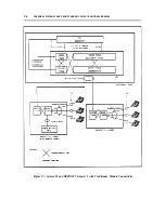
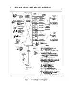
Figure 1-1, System 85 and DEFINITY Generic 2 with Traditional Module Connectivity illustrates the
connections for a basic voice path. The path flows from the point where the trunk enters the facility
through the major components of the system’s building wiring to its termination on a voice terminal at a
workstation.
The path starts on a one-pair circuit that runs from the CO to the equipment room. In the equipment
room, the wire terminates at the network interface. A connection using jumper wire or patchcord is
Summary of Contents for 9601
Page 1: ...555 104 630 Issue 2 June 1991 DEFINITY Communications SystemGeneric 2 and System 85 Wiring ...
Page 57: ...2 34 MDF IDF DESIGN SYSTEM 85 AND DEFINITY GENERIC 2 WITH TRADITIONAL MODULES ...
Page 67: ...3 10 ELECTRICAL PROTECTION SYSTEM 85 AND DEFINITY GENERIC 2 WITH TRADITIONAL MODULES ...
Page 73: ...4 6 PORT PACKS DCP REPEATERS SYSTEM 85 AND DEFINITY GENERIC 2 WITH TRADITIONAL MODULES ...
Page 85: ...6 6 OVERVIEW DEFINITY GENERIC 2 WITH UNIVERSAL MODULES ...
Page 119: ...7 34 MDF lDF DESIGN DEFINITY GENERIC 2 WITH UNIVERSAL MODULES ...
Page 123: ...8 4 ELECTRICAL PROTECTION DEFINlTY GENERIC 2 WITH UNIVERSAL MODULES ...
Page 135: ...10 8 INSTALLATION EXAMPLE DEFINITY GENERIC 2 WITH UNIVERSAL MODULES ...
Page 139: ...11 4 BRI DEFINITY GENERIC 2 WITH UNIVERSAL MODULES ...
Page 174: ...GL 12 GLOSSARY ...

