2. MDF/IDF DESIGN: SYSTEM 85 AND DEFINITY GENERIC 2
WITH TRADITIONAL MODULES
This chapter recommends the terminal blocks and frames best suited for constructing a main distribution
frame (MDF) for AT&T System 85 and DEEFINITY Generic 2 (hereafter abbreviated to DEFINITY
Generic 2 or Generic 2) with traditional modules, presents the guidelines for their design, presents some
guidelines for the intermediate distribution frame (IDF) design, and briefly discusses labeling for the
MDFs and IDFs.
This chapter also presents some general guidelines, cross-connect hardware recommendations, and frame
recommendations for designing IDFs. They are simplified because IDFs, unlike the MDF, vary greatly,
and only the most general design guidelines can be applied to them.
RECOMMENDED TERMINAL BLOCKS
The two systems of AT&T cross-connect hardware that can be used to construct the cross-connect fields
in the wiring installation for a switch are the 66 system and the 110 system. For a System 85 or
DEFINITY Generic 2 with traditional modules, the 110A system, which uses jumper wires, is
recommended. The 110P system, which uses patchcords, is available, but its use is not encouraged.
The 110A comes in several models that are called terminal blocks. Each terminal block is composed of
a wiring block and a unique combination of connecting blocks. A wiring block is where the equipment,
distribution, or central office (CO) cables terminate. The connecting block, which snaps onto the front of
the wiring block, is where the jumper wires are attached to establish a path from the pairs in one cable
to the pairs in another cable.
In order to simplify the design of wiring installations, only two terminal blocks — the 110AB1-300 and
the 110AB1-100 — are recommended for System 85 and DEFINITY Generic 2 with traditional
modules. The design information contained in this guide is based upon them. The 300-pair terminal
block is preferred for the MDF and either the 100-pair or 300-pair block for the IDF.
The 110AB1-300 terminal block has a 300-pair wiring block, 60 4-pair connecting blocks, 12 5-pair
connecting blocks, and six designations strips. You can order this terminal block in connectorized or
field-terminated versions.
The 110AB1-100 terminal block has a 100-pair wiring block, 20 4-pair connecting blocks, 4 5-pair
connecting blocks, and two designations strips. You can order this terminal block also in connectorized
and field-terminated versions.
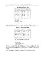
Table 2-1, 300-Pair Terminal Blocks, gives the ordering information for 300-pair terminal blocks:
2-1
Summary of Contents for 9601
Page 1: ...555 104 630 Issue 2 June 1991 DEFINITY Communications SystemGeneric 2 and System 85 Wiring ...
Page 57: ...2 34 MDF IDF DESIGN SYSTEM 85 AND DEFINITY GENERIC 2 WITH TRADITIONAL MODULES ...
Page 67: ...3 10 ELECTRICAL PROTECTION SYSTEM 85 AND DEFINITY GENERIC 2 WITH TRADITIONAL MODULES ...
Page 73: ...4 6 PORT PACKS DCP REPEATERS SYSTEM 85 AND DEFINITY GENERIC 2 WITH TRADITIONAL MODULES ...
Page 85: ...6 6 OVERVIEW DEFINITY GENERIC 2 WITH UNIVERSAL MODULES ...
Page 119: ...7 34 MDF lDF DESIGN DEFINITY GENERIC 2 WITH UNIVERSAL MODULES ...
Page 123: ...8 4 ELECTRICAL PROTECTION DEFINlTY GENERIC 2 WITH UNIVERSAL MODULES ...
Page 135: ...10 8 INSTALLATION EXAMPLE DEFINITY GENERIC 2 WITH UNIVERSAL MODULES ...
Page 139: ...11 4 BRI DEFINITY GENERIC 2 WITH UNIVERSAL MODULES ...
Page 174: ...GL 12 GLOSSARY ...

