background image

Required equipment

To move the secondary backplane connector, you need a Phillips No. 1 screwdriver. A pair of
needle-nosed pliers can also be helpful for removing the pin connector.

To prepare the 201i server for installation in a Meridian 1 switch

1. Remove the secondary backplane pin connector.

The pin connector has four pins. If necessary, use needle-nosed pliers to remove it.

2. Remove the top and bottom screws that hold the secondary backplane connector

in place on the stiffening cage.

3. Loosen the middle screw, and then align the outside pair of screw holes on the

bracket with the matching pair on the stiffening cage.

4. Replace and alternately tighten all screws until the connector is evenly and securely

fastened.

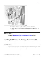
See the following diagram:

Required equipment

Avaya CallPilot

®

 201i Server Hardware Installation

December 2010     41

Summary of Contents for CallPilot 201i

Page 1: ...Avaya CallPilot 201i Server Hardware Installation 5 0 NN44200 301 01 03 December 2010 ...

Page 2: ...G THE SOFTWARE HEREINAFTER REFERRED TO INTERCHANGEABLY AS YOU AND END USER AGREE TO THESE TERMS AND CONDITIONS AND CREATE A BINDING CONTRACT BETWEEN YOU AND AVAYA INC OR THE APPLICABLE AVAYA AFFILIATE AVAYA Copyright Except where expressly stated otherwise no use should be made of materials on this site the Documentation Software or Hardware provided by Avaya All content on this site the documenta...

Page 3: ...I O cable description 22 Peripheral connectivity 24 Introduction 24 Faceplate connections 24 Monitor keyboard and mouse 25 MPC 8 card 25 SCSI connections 25 Supported peripheral devices 26 CD ROM drive NTRH9037 26 Tape drive NTRH9038 26 Modem 26 10Base T Ethernet hub or switch 27 Monitor keyboard and mouse 27 Chapter 3 Preparing for installation 29 In this chapter 29 Installation overview 29 Intro...

Page 4: ...ou begin 45 What is next 47 Installing the NTRH3501 backplane cable 48 Introduction 48 Backplane tip and ring cable 48 Before you begin 49 What is next 50 Installing the SCSI cables for Meridian 1 51 Introduction 51 Cables you need 51 What the completed installation looks like 52 Before you begin 53 What is next 55 Chapter 5 Installing the 201i server in an Option 11C or Option 11C Mini 57 In this...

Page 5: ...ction 80 What is next 82 Installing the 201i server 82 Introduction 82 Before you begin 83 What is next 84 Installing the NTRH3502 SCSI cable for Communication Server 1000 85 Introduction 85 CD ROM and tape drive cabling diagram 85 Before you begin 86 What is next 88 Replacing the Media Gateway or Media Gateway Expansion cover 88 Introduction 88 To replace the inside front cover plate 88 What is n...

Page 6: ...nd mouse 108 Modem 109 201i server faceplate and peripheral device connectors 109 Starting the 201i server 110 Before you begin 110 Installing the MPCs 110 Introduction 110 Correct card insertion 111 What is next 112 Installing the monitor keyboard and mouse 113 Introduction 113 Hardware requirement 113 PS 2 extension cable 113 What is next 114 Connecting the CD ROM and tape drives 114 Introductio...

Page 7: ...Introduction 126 To complete the installation and start the 201i server 126 What is next 127 Index 129 Avaya CallPilot 201i Server Hardware Installation December 2010 7 ...

Page 8: ...8 Avaya CallPilot 201i Server Hardware Installation December 2010 ...

Page 9: ...nd print selected technical publications and release notes directly from the Internet go to www avaya com support Getting product training Ongoing product training is available For more information or to register you can access the Web site at www avaya com support From this Web site you can locate the Training contacts link on the left hand navigation pane Getting help from a distributor or resel...

Page 10: ... Web site The easiest and most effective way to get technical support for Avaya products is from the Avaya Technical Support Web site at www avaya com support Customer service 10 Avaya CallPilot 201i Server Hardware Installation December 2010 ...

Page 11: ...s of a Meridian 1 shelf or Communication Server 1000 Media Gateway or Media Gateway Expansion When the server is locked into position its connectors attach to the backplane which provides power and communications links Customer Documentation Map The following diagram shows the overall organization and content of the CallPilot documentation suite Table 1 CallPilot Customer Documentation Map Fundame...

Page 12: ...llation Guides Avaya CallPilot 201i Server Hardware Installation Guide NN44200 301 Avaya CallPilot 202i Server Hardware Installation Guide NN44200 317 Avaya CallPilot 202i Installer Roadmap NN44200 319 Avaya CallPilot 703t Server Hardware Installation Guide NN44200 304 Avaya CallPilot 1002rp Server Hardware Installation Guide NN44200 300 Avaya CallPilot 1002rp System Evaluation NN44200 318 Avaya C...

Page 13: ... and Diagnostics Avaya CallPilot 201i Server Maintenance and Diagnostics Guide NN44200 705 Avaya CallPilot 202i Server Maintenance and Diagnostics Guide NN44200 708 Avaya CallPilot 703t Server Maintenance and Diagnostics Guide NN44200 702 Avaya CallPilot 1002rp Server Maintenance and Diagnostics Guide NN44200 701 Avaya CallPilot 1005r Server Maintenance and Diagnostics Guide NN44200 704 Avaya Call...

Page 14: ...NN44200 110 The Map was created to facilitate navigation through the suite by showing the main task groups and the documents contained in each category It appears near the beginning of each guide showing that guide s location within the suite Primary components The 201i server motherboard houses the interfaces needed to communicate with the Meridian 1 switch or Communication Server 1000 system to ...

Page 15: ...must move the secondary backplane DS30X connector to the correct position For more information see Repositioning the secondary backplane connector on page 39 The following diagram shows the 201i server components Faceplate The following diagram shows the 201i server faceplate The faceplate provides LEDs MPC card slots and connectors for peripheral devices Faceplate Avaya CallPilot 201i Server Hard...

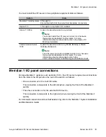
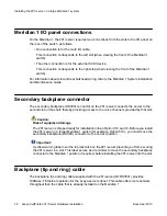
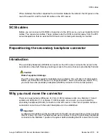
Page 16: ...he server to the backplane of the Meridian 1 switch or the backplane of the Communication Server 1000 Media Gateway or Media Gateway Expansion Keyboard connector The keyboard connector is a standard PS 2 connector and is hot pluggable Infrared port For future use Monitor connector The monitor connector is a standard high density 15 pin female connector About the 201i server 16 Avaya CallPilot 201i...

Page 17: ...del Server Maintenance and Diagnostics guide for your server MPC card ejector buttons There is one ejector button for each MPC card slot When you insert the card the associated ejector button pops out Press the button to eject the card from its slot MPC card slots MPCs house DSP units and are used for multimedia telephony processing You can install up to four MPCs on the 201i server The 201i is sh...

Page 18: ...ess the reset button you must shut down the operating system Press the reset button while the operating system is running only when you cannot shut down the operating system normally Environmental specifications Temperatures Recommended temperature 15 C 59 F to 30 C 86 F Absolute temperature 10 C 50 F to 45 C 113 F Long term storage temperature 20 C 4 F to 60 C 140 F Short term storage temperature...

Page 19: ...on Important To secure the CallPilot server from unauthorized access ensure that the CallPilot network is inside your organization s firewall Sample network setup Meridian 1 switch The following diagram shows how the 201i server is integrated into your network with the following Meridian 1 switches large systems such as Option 51C Option 11C Option 11C Mini Network connectivity Avaya CallPilot 201...

Page 20: ...erver 1000 The following diagram shows an example of how the 201i server can be integrated with the Communication Server 1000 system in your network About the 201i server 20 Avaya CallPilot 201i Server Hardware Installation December 2010 ...

Page 21: ...dwidth and network requirements refer to the Communication Server 1000 Planning and Installation Guide For a description of each Communication Server 1000 system component see Communication Server 1000 description on page 75 CallPilot Avaya server subnet and ELAN subnet setup The 201i server supports the following network protocols CLAN 10 100Base T Ethernet A built in Ethernet controller on the 2...

Page 22: ...O cable description on page 22 Network requirements Appropriate networking equipment must be available for both the Avaya server subnet and ELAN subnet The Avaya server subnet and ELAN subnet must be properly configured for correct CallPilot operation To ensure correct configuration Avaya recommends that you consult a network specialist Important For important considerations about using the ELAN s...

Page 23: ...witches and modem 10Base T RJ 45 This connector provides a 10 Mbit s Ethernet connection between the 201i server and the Meridian 1 switch or Communication Server 1000 system This connection allows the exchange of call control information between the server and the Meridian 1 switch or Communication Server 1000 system For more information about the ELAN subnet see the CallPilot Installation and Co...

Page 24: ... and technical support personnel to administer the 201i server from a remote location Peripheral connectivity Introduction Peripheral equipment is attached to the 201i server on the server faceplate Faceplate connections Important Connections made to the faceplate with the exceptions noted below are temporary only because you must remove the cabinet cover to make these connections The system does ...

Page 25: ...ype II PC cards into MPC 8 card slots They are not compatible SCSI connections The SCSI connection is the only permanent faceplate connection A low profile right angle connector on the SCSI cable allows the cable to be attached with the cabinet covers on For more information about how the 201i server and SCSI device connections are achieved see large Meridian 1 systems for example Option 51C Insta...

Page 26: ...nal SCSI tape drive is used to back up and restore data The device connects to the server by an intermediate SCSI cable that connects to the SCSI connector on the faceplate Since the tape drive is an external device it requires an AC power source Set the SCSI ID for the tape drive to 5 If you are connecting more than one SCSI device to the server such as a CD ROM drive you must daisy chain those d...

Page 27: ... in monitor NTRH9011 or N0038380 LCD monitor Since the monitor is an external device it requires an AC power source Keyboard NTRH9013 Mouse NTRH9014 Note The mouse connector on the 201i faceplate is a PS 2 connector If you plan to use a USB mouse with USB to PS 2 converter you must also use the Avaya supplied 101 mm 4 in PS 2 extension cable A0855616 Without the extension cable the monitor connect...

Page 28: ...About the 201i server 28 Avaya CallPilot 201i Server Hardware Installation December 2010 ...

Page 29: ...lPilot server and its associated peripherals Power for these devices must be wired and fused independently of all other receptacles and referenced to the same ground as the PBX system A qualified electrician must implement the single point ground reference as required between the power outlets of the Avaya CallPilot server and the power outlets of the switch Provide a sufficient number of properly...

Page 30: ...e 32 Complete the following checklists that are provided in the CallPilot Installation and Configuration Task List CallPilot software media and documentation checklist CallPilot server hardware checklist Inspect the server for any damage that might have occurred during shipping see Unpacking and inspecting the 201i server on page 32 2 Familiarize yourself with the Switch and network requirements o...

Page 31: ...e drives see pages Setting the CD ROM drive SCSI ID and DIP switches on page 98 and Setting the tape drive SCSI ID on page 100 DIP switches on the CD ROM drive see Setting the CD ROM drive SCSI ID and DIP switches on page 98 device termination on the CD ROM and tape drives see Setting SCSI device termination on page 101 7 Insert the 201i server into two consecutive slots inside the switch For inst...

Page 32: ...ting the modem on page 124 Connect the power cords for all devices and then power them up 10 Complete the installation of the 201i server as follows Connect the intermediate SCSI cable to the 201i server faceplate Close the lock latches on the 201i server Boot the 201i server to the operating system See Completing the installation on page 126 11 Continue with the CallPilot switch model and CallPil...

Page 33: ...ion on page 11 and perform a visual inspection as described in To inspect the 201i server for shipping damage on page 33 To inspect the 201i server for shipping damage Before proceeding with the installation visually inspect the 201i server for any damage that might have occurred during shipping Ensure also that the items in the following checklists are secure Item Yes No Are all cables securely s...

Page 34: ...t Review the Switch and network requirements on page 34 Switch and network requirements Introduction The information in this section will help you plan your 201i server installation Meridian 1 or Communication Server 1000 slot requirements The 201i server occupies two physical and electrical slots Note You can place the unit in Slot 9 of an Option11C as the unit can function from slots 9 and 10 Do...

Page 35: ...because these slots are dedicated to other cards For more information about cards and slots refer to the Communication Server 1000 Planning and Installation Guide Meridian 1 I O panel connections On large Meridian 1 systems such as Option 51C the 201i server requires two connections from the slots to the I O panel on the rear of the switch as follows One connection is for the multi I O cable This ...

Page 36: ...List What is next Install the 201i server in the Meridian 1 switch or Communication Server 1000 system For instructions see one of the following To install the 201i server in See a large Meridian 1 switch for example Option 51C Installing the 201i server in a large Meridian 1 system on page 37 an Option 11C or Option 11C Mini switch Installing the 201i server in an Option 11C or Option 11C Mini on...

Page 37: ...ling the SCSI cables for Meridian 1 on page 51 Overview Introduction This section describes how to install the 201i server in a Meridian 1 switch Important To install the 201i server in an Option 11C go to Installing the 201i server in the large Meridian 1 switch on page 43 For Option 11C Mini go to Section B Installing Option 11C Mini cables on page 65 For Communication Server 1000 go to Installi...

Page 38: ...hat slot Caution Risk of equipment damage The 201i server is shipped ready for installation into an Option 11C switch Before you install the 201i server in a larger Meridian 1 switch for example Option 51C you must move the secondary backplane DS30X connector to the correct position Important A yellow warning label over the top lock latch on the 201i server prevents you from securing the 201i serv...

Page 39: ...ation into an Option 11C or Option 11C Mini switch Before you install the 201i server in a larger Meridian 1 switch for example Option 51C you must move the secondary backplane DS30X connector to the correct position Why you must move the connector There is an approximate difference of 2 mm 0 08 in between slots on a Meridian 1 tiered system and an Option 11C or Option 11C Mini system As a result ...

Page 40: ...th four pins Two pairs of screw holes are provided for connecting the secondary backplane connector to the 201i server stiffening cage The outside pair provides the Meridian 1 spacing The inside pair provides the Option 11C or Option 11C Mini spacing See the following diagram Installing the 201i server in a large Meridian 1 system 40 Avaya CallPilot 201i Server Hardware Installation December 2010 ...

Page 41: ...s four pins If necessary use needle nosed pliers to remove it 2 Remove the top and bottom screws that hold the secondary backplane connector in place on the stiffening cage 3 Loosen the middle screw and then align the outside pair of screw holes on the bracket with the matching pair on the stiffening cage 4 Replace and alternately tighten all screws until the connector is evenly and securely faste...

Page 42: ...ugh both connectors Ensure that the connectors are correctly aligned as shown in the diagram below Caution Risk of equipment damage Installing the 201i server in a large Meridian 1 system 42 Avaya CallPilot 201i Server Hardware Installation December 2010 ...

Page 43: ...inue with Installing the 201i server in the large Meridian 1 switch on page 43 Installing the 201i server in the large Meridian 1 switch Introduction The 201i server occupies two slots You can install the 201i server in slots 0 through 14 Ensure that both slots have electrical backplane connectivity What is next Avaya CallPilot 201i Server Hardware Installation December 2010 43 ...

Page 44: ...lots Important Do not push the 201i server into place against the backplane until you are ready to observe the startup cycle The 201i server receives power and starts as soon as the 201i server makes contact with the switch backplane 4 Connect the low profile right angle SCSI cable connector to the SCSI connector on the 201i server faceplate What is next Continue with Removing the backplane tip an...

Page 45: ...el only The backplane connectors associated with the right slot are left vacant These cables are supplied with the 201i server Before you begin Voltage Risk of electrical shock Ensure that the shelf is powered off before you remove the backplane cables Note For information about slot and rear bulkhead wiring and powering off the shelf refer to the Meridian 1 System Installation and Maintenance Gui...

Page 46: ...eplace the connector shroud Remove the tie wraps where applicable to free the cable c Remove the connector I O filter assembly and all mounting hardware from the inside of the I O panel so the slot is completely vacated Retain the mounting hardware that is screws tie wrap base standoffs and so on You will reuse this hardware to fasten the NTRH3501 cable 4 Repeat step 3 on page 46 to remove the exi...

Page 47: ...What is next Continue with Installing the NTRH3501 backplane cable on page 48 What is next Avaya CallPilot 201i Server Hardware Installation December 2010 47 ...

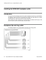
Page 48: ...oughput than the cable you just removed from the Meridian 1 When installed this cable completes the connection between the left slot the I O panel on the rear of the switch and the multi I O cable on the 201i server Backplane tip and ring cable The following diagram shows the NTRH3501 backplane tip and ring cable Installing the 201i server in a large Meridian 1 system 48 Avaya CallPilot 201i Serve...

Page 49: ...to the tie wrap base and fasten the screw into the lower position of the I O panel slot b Attach the three inner cables to the backplane connectors associated with the left slot as follows UP 1 cable to the top position UP 2 cable to the middle position UP 3 cable to the lower position Important The connectors are keyed you can insert them in one position only Use tie wraps to secure the cables in...

Page 50: ...What is next Continue with Installing the SCSI cables for Meridian 1 on page 51 Installing the 201i server in a large Meridian 1 system 50 Avaya CallPilot 201i Server Hardware Installation December 2010 ...

Page 51: ...ent damage You must power off the 201i server before connecting or disconnecting SCSI cables Cables you need You require the following cables NTRH1408 for connecting the 201i server to the Meridian 1 I O panel The connector on the intermediate SCSI cable that attaches to the 201i server faceplate is a low profile right angle connector This allows the cable to be attached with the Meridian 1 cabine...

Page 52: ...hat the completed installation looks like The following diagram shows how the intermediate SCSI cable CD ROM drive and tape drive are connected to the Meridian 1 In this diagram the CD ROM drive is the first device The tape drive is the last device Installing the 201i server in a large Meridian 1 system 52 Avaya CallPilot 201i Server Hardware Installation December 2010 ...

Page 53: ...structions refer to Preparing peripheral devices on page 95 To install the SCSI cables for Meridian 1 1 Thread the SCSI connector end of the NTRH1408 cable from the front of the Meridian 1 along the bottom of the shelf to either the left or the right access channel 2 Leave the low profile right angle SCSI connector hanging for now You will connect it later to the 201i server faceplate Note The fol...

Page 54: ...to the inside of the I O panel slot associated with the 201i server right slot 5 Connect the NTRH1410 cable to the NTRH1408 cable connector on the I O panel See the following diagram Installing the 201i server in a large Meridian 1 system 54 Avaya CallPilot 201i Server Hardware Installation December 2010 ...

Page 55: ... through the bottom of the Meridian 1 tower 7 Replace the protective plate 8 Replace the I O panel cover 9 Power up the shelf What is next Prepare the modem CD ROM drive and tape drive for connection to the 201i server For instructions see Preparing peripheral devices on page 95 What is next Avaya CallPilot 201i Server Hardware Installation December 2010 55 ...

Page 56: ...Installing the 201i server in a large Meridian 1 system 56 Avaya CallPilot 201i Server Hardware Installation December 2010 ...

Page 57: ...on page 65 Installing cables on the back of the Option 11C Mini cabinet on page 71 Installing the 201i server in the Option 11C or Option 11C Mini switch Introduction The 201i server occupies physical and electrical slots The 201i server must be installed in two peripheral equipment slots as follows Switch Eligible slots Option 11C Slots 1 through 9 in any cabinet Option 11C Mini A pair of consecu...

Page 58: ...g a Loosen the spring loaded clips b Slide the cover to the left c Pull the cover up to remove it from the cabinet See the following diagram 2 Ensure that no cables are connected to the slots in which you are installing the 201i server 3 Open the lock latches at the top and bottom of the 201i server faceplate Installing the 201i server in an Option 11C or Option 11C Mini 58 Avaya CallPilot 201i Se...

Page 59: ... that the 201i server is positioned correctly between the slots Note When correctly inserted in the Option 11C Mini the top of the 201i server is on the left See the following diagram Important Do not push the 201i server into place against the backplane until you are ready to observe the startup cycle The 201i server receives power and starts as soon as the 201i server makes contact with the swit...

Page 60: ...D ROM or tape drive to the 201i server Option 11C requires an intermediate SCSI cable NTRH1407 Note If you are installing the 201i server in an Option 11C Mini go to Installing the NTRH3502 SCSI cable for Option 11C Mini on page 65 Cable description The connector on the NTRH1407 cable that attaches to the 201i server faceplate is a low profile right angle connector This allows the SCSI device to b...

Page 61: ...th the NTRH3502 cable that is provided with the device What the completed installation looks like The following diagram shows how the intermediate SCSI cable CD ROM drive and tape drive are connected to the Option 11C The CD ROM drive is the first device The tape drive is the last device What the completed installation looks like Avaya CallPilot 201i Server Hardware Installation December 2010 61 ...

Page 62: ...reparing peripheral devices on page 95 To install the cable 1 Caution Risk of equipment damage You must power off the 201i server before connecting or disconnecting SCSI cables Attach the bracket assembly and cable as follows a Below the card cage temporarily remove the hardware that secures cable connections to the Option 11C b Temporarily remove any cabling that may interfere with the installati...

Page 63: ... removed previously so that the SCSI connector appears on the right side of the Option 11C cabinet See the following diagram 2 Thread the cable up through the card cage Note When routing the SCSI cable through the card cage ensure the second cable ferrite is placed halfway through the opening 3 Connect the grounding braid on the intermediate SCSI cable to the card cage and tighten the screw Before...

Page 64: ...ce all cabling and hardware that you removed in step 1 on page 62 6 Restore any services that you took out of service in step 1 on page 62 What is next Prepare the modem CD ROM drive and tape drive for connection to the 201i server For instructions see Preparing peripheral devices on page 95 Installing the 201i server in an Option 11C or Option 11C Mini 64 Avaya CallPilot 201i Server Hardware Inst...

Page 65: ...cted If the Option 11C Mini is equipped with a Fiber Routing Guide consisting of a spool and mounting bracket you must remove it before you can install the NTRH3502 SCSI cable and then reinstall it when you are finished For detailed instructions on removing and installing the Fiber Routing Guide refer to the Option 11C and Option 11C Mini Expansion Guide What the completed installation looks like ...

Page 66: ...daisy chain you must configure the SCSI device IDs and DIP switches For instructions see Preparing peripheral devices on page 95 To install the NTRH3502 SCSI cable 1 Caution Risk of equipment damage You must power off the 201i server before connecting or disconnecting SCSI cables If your Option 11C Mini is equipped with a Fiber Routing Guide temporarily remove it Installing the 201i server in an O...

Page 67: ...Option 11C and Option 11C Mini Expansion Guide See the following diagram 2 Remove the inner SCSI bracket from the inside of the cabinet See the following diagram Before you begin Avaya CallPilot 201i Server Hardware Installation December 2010 67 ...

Page 68: ...ire 4 Connect the low profile right angle SCSI connector on the NTRH3502 cable to the SCSI connector on the 201i server faceplate 5 Fasten the SCSI cable drain wire to the top screw that previously held the inner SCSI bracket in place Installing the 201i server in an Option 11C or Option 11C Mini 68 Avaya CallPilot 201i Server Hardware Installation December 2010 ...

Page 69: ...outing Guide 6 If required reinstall the Fiber Routing Guide Note For detailed instructions refer to the Option 11C and Option 11C Mini Expansion Guide See the following diagram Before you begin Avaya CallPilot 201i Server Hardware Installation December 2010 69 ...

Page 70: ... What is next Continue with Installing cables on the back of the Option 11C Mini cabinet on page 71 Installing the 201i server in an Option 11C or Option 11C Mini 70 Avaya CallPilot 201i Server Hardware Installation December 2010 ...

Page 71: ...i cabinet locate the connector associated with the first slot occupied by the 201i server 2 Connect the NTRH0912 multi I O cable as follows a Loosen the connector s Velcro fastening strap b Connect the amphenol connector on the NTRH0912 multi I O cable to the connector on the back of the Option 11C Mini cabinet c Secure the connection by tightening the retaining screw and Velcro fastening strap of...

Page 72: ...e cabinet See the diagram in step 4 on page 72 4 Connect the power cord to the Option 11C Mini cabinet See the following diagram Installing the 201i server in an Option 11C or Option 11C Mini 72 Avaya CallPilot 201i Server Hardware Installation December 2010 ...

Page 73: ...pare the modem CD ROM drive and tape drive for connection to the 201i server For instructions see Preparing peripheral devices on page 95 What is next Avaya CallPilot 201i Server Hardware Installation December 2010 73 ...

Page 74: ...Installing the 201i server in an Option 11C or Option 11C Mini 74 Avaya CallPilot 201i Server Hardware Installation December 2010 ...

Page 75: ...1000 on page 85 Replacing the Media Gateway or Media Gateway Expansion cover on page 88 Connecting cables to the Communication Server 1000 system on page 91 Communication Server 1000 description Introduction The Communication Server 1000 system is an IP PBX that provides telephony and data capabilities over an IP network The Communication Server 1000 system consists of the following major componen...

Page 76: ...omer supplied standard 100Base T CAT5 Ethernet cables for point to point connections Avaya supplied crossover Ethernet cables one 10Base T Ethernet connector that provides the ELAN subnet interface to management software applications such as Optivity Telephony Manager and Avaya CallPilot accepts an industry standard Medium Access Unit MAU one SDI connector that interfaces with three TTY ports usin...

Page 77: ...slots into which you can install the CallPilot 201i server Unit The 201i server can be installed in Ineligible slots Media Gateway Slots 1 and 2 Slots 2 and 3 Slots 3 and 4 Slot 0 is dedicated to the SSC card Media Gateway Expansion Slots 7 and 8 Slots 8 and 9 Slots 9 and 10 Slot 10 is a double wide slot The second half of this slot does not have a backplane connector For more information about ca...

Page 78: ...ary AUX connector yes no One SDI connector yes no One 10Base T Ethernet connector that provides the ELAN subnet interface to management software applications such as Optivity Telephony Manager and CallPilot accepts an industry standard Medium Access Unit MAU yes no DS30X and CE MUX connectors for connecting the Media Gateway and Media Gateway Expansions together yes yes Power connector yes yes The...

Page 79: ...anagement Configuration required for correct CallPilot operation is therefore performed on the Call Server Administration software The Communication Server 1000 system interfaces with Optivity Telephony Manager Release 1 1 or later Optivity Telephony Manager is an integrated suite of system management tools You can use Optivity Telephony Manager to configure control and manage your Communication S...

Page 80: ...t Output X21 Administration Communication Server 1000 Input Output X21 Maintenance You can search the entire suite of documentation online or you can print part or all of a guide Removing the Media Gateway or Media Gateway Expansion cover Introduction To access the interior of the Media Gateway or Media Gateway Expansion you must remove the front bezel and inside front cover plate To remove the fr...

Page 81: ...the screwdriver handle thus applying downward pressure on the tab inside the bezel At the same time gently pull the bezel away from the chassis approximately 2 cm 0 75 in until the inside tab has cleared the catch c Grasp the bezel by both sides and carefully pull it straight away from the Media Gateway or Media Gateway Expansion 2 Remove the inside front cover plate as follows Introduction Avaya ...

Page 82: ...screw heads c Pull the inside front cover plate away from the Media Gateway or Media Gateway Expansion What is next Continue with Installing the 201i server on page 82 Installing the 201i server Introduction This section describes how to install the 201i server inside the Media Gateway or Media Gateway Expansion Installing the 201i server in the Avaya Communication Server 1000 system 82 Avaya Call...

Page 83: ...lanning and Installation Guide For the logical slot numbers that you must use when you configure the Communication Server 1000 system see Card slots on page 77 To install the 201i server inside the Media Gateway or Media Gateway Expansion 1 Ensure that no cables are connected to the slots in which you are installing the 201i server 2 Open the lock latches at the top and bottom of the 201i server f...

Page 84: ...xpansion is connected to a power source the 201i server receives power as soon as it makes contact with the backplane What is next Continue with Installing the NTRH3502 SCSI cable for Communication Server 1000 on page 85 Installing the 201i server in the Avaya Communication Server 1000 system 84 Avaya CallPilot 201i Server Hardware Installation December 2010 ...

Page 85: ...hen the Media Gateway or Media Gateway Expansion cover is installed This allows the external SCSI device to remain permanently connected to the 201i server CD ROM and tape drive cabling diagram The following diagram shows how the intermediate SCSI cable CD ROM drive and tape drive are connected to the 201i server The CD ROM drive is the first device The tape drive is the last device Installing the...

Page 86: ...ure the SCSI device IDs and DIP switches For instructions see Preparing peripheral devices on page 95 To install the NTRH3502 cable 1 Caution Risk of equipment damage You must power off the 201i server before connecting or disconnecting SCSI cables Remove the inner SCSI bracket from the inside of the Media Gateway or Media Gateway Expansion See following diagram Installing the 201i server in the A...

Page 87: ... screws that previously held the inner SCSI bracket in place Notes Use the screw that is the most convenient Press firmly on the drain wire Y connector until it snaps into place around the screw post 5 Replace the inside front cover plate For instructions see To replace the inside front cover plate on page 88 Important Ensure that the tabs on the bottom and right side of the inside front cover pla...

Page 88: ... or Media Gateway Expansion cover Introduction This section describes how to replace the front bezel and inside front cover plate on the Media Gateway or Media Gateway Expansion To replace the inside front cover plate The following diagram provides an overview of how to install the inside front cover plate Installing the 201i server in the Avaya Communication Server 1000 system 88 Avaya CallPilot ...

Page 89: ... behind the side rail 4 Tighten the screws to secure the front cover plate 5 Continue with To replace the front bezel on page 89 below To replace the front bezel 1 Warning Risk of eye injury Avaya recommends that you operate the Media Gateway and Media Gateway Expansion with their front bezels installed When the blue LEDs inside these units are lit they are very bright To replace the inside front ...

Page 90: ...l toward the Media Gateway or Media Gateway Expansion until it snaps into place 3 Replace the label What is next Continue with Connecting cables to the Communication Server 1000 system on page 91 Installing the 201i server in the Avaya Communication Server 1000 system 90 Avaya CallPilot 201i Server Hardware Installation December 2010 ...

Page 91: ...nect the cables 1 On the rear of the Media Gateway or Media Gateway Expansion locate the connector associated with the first slot occupied by the 201i server 2 Connect the NTRH0912 multi I O cable as follows a Loosen the connector s Velcro fastening strap b Connect the amphenol connector on the NTRH0912 multi I O cable to the connector on the back of the Media Gateway or Media Gateway Expansion c ...

Page 92: ...r Media Gateway Expansion See the diagram in step 4 on page 92 4 Connect the power cord to the Media Gateway or Media Gateway Expansion Installing the 201i server in the Avaya Communication Server 1000 system 92 Avaya CallPilot 201i Server Hardware Installation December 2010 ...

Page 93: ...pare the modem CD ROM drive and tape drive for connection to the 201i server For instructions see Preparing peripheral devices on page 95 What is next Avaya CallPilot 201i Server Hardware Installation December 2010 93 ...

Page 94: ...Installing the 201i server in the Avaya Communication Server 1000 system 94 Avaya CallPilot 201i Server Hardware Installation December 2010 ...

Page 95: ...nnected to the 201i server intermediate SCSI cable If there is more than one SCSI device the devices are daisy chained together Each device on the SCSI bus must have a unique SCSI ID and only the last device in the chain is terminated Supported SCSI devices You need an external CD ROM drive to upgrade reinstall and configure the 201i server Since the CD ROM drive is an external device it requires ...

Page 96: ...LR5 tape drive Note This is currently the only supported tape drive DIP switches SCSI ID and SCSI device termination settings For correct operation with the 201i server you must set the following DIP switches on the modem and CD ROM drive SCSI ID and device termination on the CD ROM and tape drives Setting the modem DIP switches Introduction Set the modem DIP switches to their default settings Thi...

Page 97: ... DTR override 2 OFF Verbal numeric result codes OFF Displays verbal word results ON Displays numeric results 3 ON Result code display OFF Suppresses result codes ON Enables result codes 4 OFF Command mode local echo suppression OFF Displays keyboard commands ON Suppresses echo 5 ON Auto answer suppression OFF Modem answers on first ring or higher if specified in NVRAM ON Disables auto answer 6 OFF...

Page 98: ...scribes how to set the CD ROM drive SCSI ID and DIP switches Important You must power down the CD ROM drive before changing the SCSI ID and DIP switches Note The CD ROM drive discussed in this section is the external SCSI CD ROM drive NTRH9037 To set the CD ROM drive SCSI ID The SCSI ID setting is located on the back of the CD ROM drive See the diagram that follows To change the SCSI ID use the bl...

Page 99: ...OM drive is the first and only device set this switch to ON If the CD ROM drive is the first device and daisy chained with the tape drive set this switch to OFF 3 Test OFF for factory use only 4 Block OFF 5 Eject OFF Note If this switch is set to ON the eject button on the CD ROM drive is disabled To eject the CD ROM from the drive a software eject command must be sent over the SCSI bus To set the...

Page 100: ... The tape drive discussed in this section is the Tandberg SLR5 tape drive NTRH9038 This is currently the only supported tape drive To set the tape drive SCSI ID The SCSI ID setting is located on the back of the tape drive See the following diagram Note The appearance and size of the tape drive cabinet is subject to change The diagram is an example of the key components To change the SCSI ID use th...

Page 101: ...enarios The first device in a SCSI device daisy chain can be either the tape drive or the CD ROM drive However because the Tandberg SLR5 tape drive is already internally terminated at the factory Avaya recommends that you connect the tape drive as the last device The following diagrams show the supported daisy chain and SCSI cable connections for your switch The CD ROM drive is the first device in...

Page 102: ...n 11C Option 11C Mini For more information about the cabling requirements see one of the following Installing the intermediate SCSI cable for Option 11C on page 60 Installing the NTRH3502 SCSI cable for Option 11C Mini on page 65 Preparing peripheral devices 102 Avaya CallPilot 201i Server Hardware Installation December 2010 ...

Page 103: ... For more information about the cabling requirements see Installing the NTRH3502 SCSI cable for Communication Server 1000 on page 85 Communication Server 1000 Avaya CallPilot 201i Server Hardware Installation December 2010 103 ...

Page 104: ...rnal termination is not required because the drive is already internally terminated This is indicated by a label on the back or front of the tape drive both a CD ROM drive and a tape drive the tape drive is the last device set DIP switch 2 on the back of the CD ROM drive to OFF The tape drive is internally terminated External termination is not required Preparing peripheral devices 104 Avaya CallP...

Page 105: ... is next Complete the 201i server installation in the switch See Connecting peripheral devices to the 201i server on page 107 What is next Avaya CallPilot 201i Server Hardware Installation December 2010 105 ...

Page 106: ...Preparing peripheral devices 106 Avaya CallPilot 201i Server Hardware Installation December 2010 ...

Page 107: ... and Avaya server subnet on page 121 Connecting the modem on page 124 Completing the installation on page 126 Overview Introduction This section describes installing the 201i server in the switch connecting peripheral devices and starting the 201i server Connecting the 201i server to the network The switch ELAN subnet Avaya server subnet and modem connections are established by using the 201i serv...

Page 108: ...ensure that you have set the SCSI ID termination and DIP switches as described in Preparing peripheral devices on page 95 Monitor keyboard and mouse Connect the monitor keyboard and mouse to the 201i server faceplate so that you can observe the 201i server startup process run the Configuration Wizard perform initial administration after installation The 201i server is not intended to operate with ...

Page 109: ...s not have access to the Avaya server subnet you need assistance from Avaya technical support 201i server faceplate and peripheral device connectors The following diagram identifies the peripheral device connectors and slots on the 201i server faceplate Modem Avaya CallPilot 201i Server Hardware Installation December 2010 109 ...

Page 110: ...fore you connect the peripheral devices ensure that you have completed the following tasks 1 Set the DIP switches on the external fax modem See Setting the modem DIP switches on page 96 2 Prepare the SCSI CD ROM and tape drives See the following Setting the CD ROM drive SCSI ID and DIP switches on page 98 Setting the tape drive SCSI ID on page 100 Setting SCSI device termination on page 101 Instal...

Page 111: ...1 Do one of the following IF THEN MPCs are already installed ensure that they are firmly seated in their slots you want to install additional MPCs continue with the rest of this procedure 2 Ensure that the MPC 8 card label is facing one of the following ways facing up if the 201i server is lying horizontally on a flat surface with the top lock latch on the left facing to the right if the 201i serv...

Page 112: ...tton pops back out Note Populate MPC slots in numerical order as listed on the 201i server faceplate What is next Continue with Installing the monitor keyboard and mouse on page 113 Connecting peripheral devices to the 201i server 112 Avaya CallPilot 201i Server Hardware Installation December 2010 ...

Page 113: ...a web browser on a PC that is connected to the ELAN subnet or Avaya server subnet Hardware requirement Caution Risk of equipment damage The mouse connector on the 201i faceplate is a PS 2 connector If you plan to use a USB mouse with USB to PS 2 converter you must also use the Avaya supplied 4 inch PS 2 extension cable A0855616 Without the extension cable the USB to PS 2 mouse connector is partial...

Page 114: ... to the 201i server faceplate using standard PS 2 connectors What is next Continue with Connecting the CD ROM and tape drives on page 114 Connecting the CD ROM and tape drives Introduction You can connect the CD ROM tape drive or both to the intermediate SCSI cable that you installed earlier Connecting peripheral devices to the 201i server 114 Avaya CallPilot 201i Server Hardware Installation Dece...

Page 115: ...t the SCSI ID and device termination settings as described in Setting the CD ROM drive SCSI ID and DIP switches on page 98 Setting SCSI device termination on page 101 Selecting the procedure for your switch IF you are working with THEN see a large Meridian 1 switch such as Option 51 To connect the CD ROM and tape drives to the 201i server Meridian 1 on page 116 Option 11C the corresponding procedu...

Page 116: ... the NTRH1410 cable that you connected earlier to the Meridian 1 I O panel tape drive do the following a Attach the A0769312 SCSI adapter to the tape drive b Connect the SCSI adapter to the NTRH1410 cable that you connected earlier to the Meridian 1 I O panel 3 Connect the low profile right angle SCSI cable connector to the SCSI connector on the 201i server faceplate 4 Connect an additional device...

Page 117: ...CSI device 2 Follow instructions below IF the first device is the THEN CD ROM drive connect the NTRH3502 SCSI cable from the CD ROM drive to the SCSI connector that is located on the intermediate SCSI cable bracket assembly NTRH1407 on the Option 11C tape drive do the following a Attach the A0769312 SCSI adapter to the tape drive b Connect the NTRH3502 SCSI cable from the adapter to the SCSI conne...

Page 118: ...this guide If you want to use a connection scenario that is not described in this guide ensure that you use appropriate cabling for each SCSI device 5 Connect the power cord for each device 6 Power up the devices 7 Continue with What is next on page 121 To connect the CD ROM and tape drives to the 201i server Option 11C Mini 1 Connect the first SCSI device 2 Follow instructions below IF the first ...

Page 119: ...using either the SCSI cable supplied with the device or an NTRH3502 cable The following diagram shows cable connections where the CD ROM drive is the first device Note Alternate SCSI device connection scenarios are supported but are not depicted in this guide If you want to use a connection scenario that is not described in this guide ensure that you use appropriate cabling for each SCSI device 5 ...

Page 120: ...u installed earlier on the Option 11C Mini to the tape drive 3 Connect an additional device in a daisy chain if required using either the SCSI cable supplied with the device or an NTRH3502 cable The following diagram shows cable connections where the CD ROM drive is the first device Note Alternate SCSI device connection scenarios are supported but are not depicted in this guide If you want to use ...

Page 121: ...stablish the switch and network connections 1 Do one of the following IF you are installing the 201i server in a THEN large Meridian 1 for example Option 51C ensure that the 50 pin amphenol connector on the multi I O cable NTRH0912 is connected to the newly installed backplane cable NTRH3501 on the I O panel at the rear of the switch Option 11C connect the 50 pin amphenol connector on the multi I ...

Page 122: ... done so connect the amphenol connector drain wire as follows Option 11C or Meridian 1 to the nearest backplane grounding bolt on the switch The following diagram shows drain wire connection on the Option 11C Option 11C Mini or Communication Server 1000 to a screw on the back of the cabinet Connecting peripheral devices to the 201i server 122 Avaya CallPilot 201i Server Hardware Installation Decem...

Page 123: ... 4 If Avaya server subnet is required connect the connector on the multi I O cable that is labeled as CLAN to the CLAN 10 or 100Base T compliant network hub or switch What is next Continue with Connecting the modem on page 124 What is next Avaya CallPilot 201i Server Hardware Installation December 2010 123 ...

Page 124: ...1464 two 0 25 inch nuts for installation between the following RS 232 connector thumbscrews on the multi I O cable maximum length 15 m 50 ft 9 pin connector thumbscrews on the 25 pin male to 9 pin female shielded serial cable analog line jack To connect the modem 1 Ensure that the DIP switches are set as described in Setting the modem DIP switches on page 96 2 Attach the serial cable as follows a ...

Page 125: ...can damage the modem 4 Plug the power cord into an electrical outlet with an isolated ground 5 Plug the other end of the power cord into the modem power connector Result The back of the modem appears similar to the following 6 Power on the modem Note Ensure that the modem is receiving power by checking that at least one LED on its front panel is lit 7 Place the modem in an area where it cannot be ...

Page 126: ...e switch in which the 201i is installed is powered on 1 Ensure that all peripheral devices are powered up including the 201i shelf 2 Push the 201i server gently but firmly until it is flush with the backplane Result The 201i server beeps for three seconds to indicate that power is being received 3 Close the lock latches to secure the 201i server to the backplane 4 Ensure that the power status LED ...

Page 127: ...to the CallPilot server maintenance and diagnostics guide for your server for troubleshooting instructions 6 Ensure that the operating system logon window appears on the monitor If the logon window does not appear refer to the CallPilot server model Server Maintenance and Diagnostics guide for your server for troubleshooting instructions What is next Proceed with the Avaya CallPilot switch model a...

Page 128: ...Connecting peripheral devices to the 201i server 128 Avaya CallPilot 201i Server Hardware Installation December 2010 ...

Page 129: ...ctions 49 removing from Meridian 1 45 backplane connector secondary description 38 40 diagram 40 installing for Meridian1 41 43 reason for moving 39 required tools 41 booting the server 110 126 127 C cable backplane tip and ring 38 45 48 49 establishing connections 49 removing from Meridian 1 45 cable multi I O connections establishing modem 124 network 121 switch 121 connectors CLAN 22 ELAN 22 RS...

Page 130: ...erver 1000 116 Meridian 1 116 Option 11C 116 Option 11C Mini 116 keyboard 113 modem 124 monitor 113 mouse 113 network 121 123 switch 121 123 tape drive Communication Server 1000 116 Meridian 1 116 Option 11C 116 Option 11C Mini 116 connection requirements Meridian 1 35 38 connector secondary backplane description 38 40 diagram 40 installing for Meridian 1 41 43 reason for moving 39 connectors 201i...

Page 131: ...cord installation Communication Server 1000 91 SCSI cable Communication Server 1000 86 large Meridian 1 systems 51 53 Option 11C 60 62 Option 11C Mini 66 SCSI device cabling Communication Server 1000 85 116 large Meridian 1 systems 52 116 Option 11C 61 116 Option 11C Mini 65 116 secondary backplane connector 40 tape drive back panel 100 DIP switches setting CD ROM drive 99 modem 97 distributor 9 d...

Page 132: ... latches 15 M Meridian 1 backplane tip and ring cable existing cables removing 45 NTRH3501 installing 49 connection requirements 35 I O panel connections 38 network setup 19 SCSI cables installing 53 slot requirements 34 modem 26 97 124 connecting 124 connections diagram 124 DIP switches setting 97 monitor 15 25 27 113 connecting 113 connector 15 description 27 motherboard 201i server description ...

Page 133: ...rnet hub 27 keyboard 27 modem 26 monitor 27 mouse 27 tape drive 26 peripheral devices CD ROM drive 26 Ethernet hub 27 keyboard 27 modem 26 monitor 27 mouse 27 tape drive 26 power status LED description 15 protocols supported network 21 R relative humidity 201i server 18 removing the backplane tip and ring cables 45 reseller 9 reset button description 15 RS 232 connector multi I O cable 22 S SCSI c...

Page 134: ...le point ground 29 slot configuration Communication Server 1000 77 slot requirements 34 57 77 83 Communication Server 1000 77 83 small Meridian 1 systems 57 software administration 79 Communication Server 1000 requirements 79 switch connection establishing with multi I O cable 121 123 connector multi I O cable 22 requirements 34 switches setting DIP CD ROM drive 99 modem 97 T tape drive back panel...

Reviews: