Packet and serial bus maintenance
Isolating and repairing packet-bus faults
Maintenance Procedures
231
December 2003
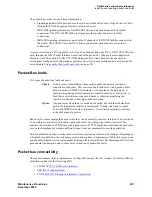
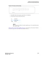
Figure 67: Stand-alone mode display
•
The symbols above the line represent specific leads on the backplane.
•
The letters below the line indicate the following:
NOTE:
This information is available only from the stand-alone mode. It is not available from the
MT or a remote login.
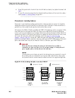
Figure 68, Packet bus leads on the backplane (front view),
on page 232 shows the location of the packet
bus leads for a given slot as seen from the front and back of the carrier.
O
Open lead
S
Shorted lead.
blank No
fault
L L L L L L L L L L H H H H H H H H H H S S S L
P 0 1 2 3 4 5 6 7 8 P 0 1 2 3 4 5 6 7 8 S F B F
_______________________________________________
S S O
Command:
Summary of Contents for CMC1
Page 1: ...Maintenance Procedures 555 245 103 Issue 1 1 December 2003 ...
Page 14: ...Contents 14 Maintenance Procedures December 2003 ...
Page 416: ...Additional maintenance procedures IP Telephones 416 Maintenance Procedures December 2003 ...
Page 426: ...Index X 426 Maintenance Procedures December 2003 ...


