Component replacement
S8300 and G700 component maintenance
296
Maintenance Procedures
December 2003
e
Unscrew the four screws on the bottom of the S8300 circuit pack that attach to the hard-
drive standoffs (Refer to
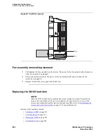
Figure 83, S8300 hard drive replacement, on page 298
f
Detach the hard-drive ribbon cable from the hard drive (leave cable attached to the S8300
circuit pack).
g
Unpack and install the new hard drive on the S8300. Standoffs for the new hard drive
should be included in the new hard drive package.
NOTE:
If standoffs are not included with the new hard drive, remove the standoffs from the old
drive and reuse them. Before screwing the standoffs into the new hard drive, clean the
threads thoroughly with a damp cloth or paper towel.
h
Screw the standoffs into the new hard drive.
CAUTION:
In
, be careful not to bend the pins on the hard drive. Leave the four jumper pins to
the right of the ribbon cable open and unconnected, as shown in
drive replacement, on page 298
i
Connect the open end of the hard-drive ribbon cable (which is attached to the S8300
circuit pack) to the replacement hard drive, as shown in
. Connect pin number one to the end of the ribbon connector
marked with the red stripe.
j
Place the hard drive on the S8300 circuit pack with the standoffs aligned with the screw
holes.
k
Hold the S8300 circuit pack on its side, with the hard drive in place, and screw the four
screws through the bottom of the S8300 circuit pack into the hard-drive standoffs.
l
If you are replacing the S8300 circuit pack, and if the CWY1 board is installed on the
original S8300, remove the CWY1 board from the original S8300 and install it on the new
S8300 circuit pack.
m Insert the S8300 into slot V1 of the G700. The LED panel (above slot V1) must be
removed and reinserted together with the S8300 circuit pack. Insert both the LED panel
and S8300 circuit pack about 1/3 of the way into the guides (the guides are in slot V1 for
the S8300 and above slot V1 for the LED panel). Push both circuit packs (together) back
into the guides, gently and firmly, until the front of each circuit pack aligns with the front
of the G700.
n
Secure the S8300 faceplate with the thumb screws. Tighten the thumb screws with a screw
driver.
5
Power up the G700 by plugging in the G700 power cord.
6
Connect your laptop to the Services port on the S8300 and access the Maintenance Web Interface.
7
Enable FTP on the S8300:
a
On the Maintenance Web Interface, select Enable/Disable Anonymous FTP under the
“Security heading
b
Click on Enable
8
Install the License and Authentication files.
Summary of Contents for CMC1
Page 1: ...Maintenance Procedures 555 245 103 Issue 1 1 December 2003 ...
Page 14: ...Contents 14 Maintenance Procedures December 2003 ...
Page 416: ...Additional maintenance procedures IP Telephones 416 Maintenance Procedures December 2003 ...
Page 426: ...Index X 426 Maintenance Procedures December 2003 ...

