Additional maintenance procedures
DS1 CPE loopback jack (T1 only)
360
Maintenance Procedures
December 2003
A problem can exist in one or more of the three sections. The field technician is responsible for finding
and correcting problems in the first two sections. The DS1 service provider is responsible for finding and
correcting problems in the third section. Testing is divided into three steps:
1
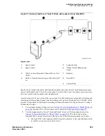
Test customer premises wiring (Span Section 1 in the following three figures) from the ICSU to
the loopback jack as described in “DS1 Span Test.”
2
Test the CO-to-network interface wiring (Section 3 in
Figure 107, Network Interface at Smart
) using the smart jack loopback (CO responsibility). Coordinate this test with
the DS1 provider.
3
Test the short length of customer premises wiring (Span Section 2 in the following three figures)
between the loopback jack and the smart jack. This can be done using a loopback that “overlaps”
section 2 of the cable. Any of the following loopbacks can do this:
a
The local ICSUs line loopback, which is typically activated, tested, and then deactivated
by the DS1 service provider at the CO end.
b
The local DS1 interface’s payload loopback, activated and tested by the DS1 service
provider at the CO end.
c
The far-end ICSU’s line loopback. This test is activated at the management terminal by
entering test ds1-loop location far-csu-loopback-test-begin. The test is terminated by
entering test ds1-loop location end-loopback/span-test. Bit error counts are examined as
described in
. This test method is the least preferable because it
covers wiring that is not in the local portion of the span. This test only isolates problems to
section 2 wiring if there are no problems in the wiring between the far-end CO and the far-
end ICSU. Coordinate this test with the DS1 service provider.
If any of the tests fails, a problem is indicated in Section 2 as long as the tests for Span Section 1
and Span Section 3 pass. Since Span Section 2 includes the network interface point, it is necessary
to work with the service provider to isolate the fault to the loopback jack cable, the “dumb” block,
or the smart jack.
Table 85: DS1 span section descriptions
Section
Smart Jack location
Section 1:
Between the 120A2 (or later) ICSU and the loopback jack
Section 2:
Between the loopback jack and the smart jack (network interface point)
Section 3:
From the smart jack to the Central Office (CO). It is necessary to contact the DS1
provider to run this test.
Summary of Contents for CMC1
Page 1: ...Maintenance Procedures 555 245 103 Issue 1 1 December 2003 ...
Page 14: ...Contents 14 Maintenance Procedures December 2003 ...
Page 416: ...Additional maintenance procedures IP Telephones 416 Maintenance Procedures December 2003 ...
Page 426: ...Index X 426 Maintenance Procedures December 2003 ...


