Issue 2 January 2008
127
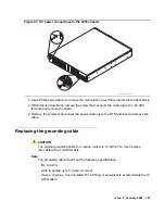
Figure 41: DC power connections to the 6350 chassis
3. Use a Phillips screwdriver to remove the clear plastic cover that protects the terminal block.
4. Within the terminal block, remove the screw that connects the cable lug to the -48 VDC
terminal and remove the cable.
5. Remove the screws that connect the power cable lug to the RTN terminal and remove the
cable.
Replacing the grounding cable
!
CAUTION:
CAUTION:
The original grounding cable for J-series routers is 14-AWG. You must replace
this cable with a 10-AWG cable.
Note:
Note:
The grounding cable must meet the following specifications:
- Be 10 AWG
- Able to handle up to 8 Amps of current
- Have a ring-type, vinyl-insulated TV14-6R lug or equivalent to accommodate the 10
AWG cable.
h
LAO 100306
3magnd2
Summary of Contents for IG550
Page 1: ...Installing and Configuring the Avaya IG550 Integrated Gateway 03 601554 Issue 2 January 2008 ...
Page 10: ...What procedure you should use 10 Installing and Configuring the IG550 Integrated Gateway ...
Page 176: ...Recovering passwords 176 Installing and Configuring the IG550 Integrated Gateway ...
Page 196: ...196 Installing and Configuring the IG550 Integrated Gateway Index ...

