IP Office Basic Edition - Quick Mode Installation
Page 68
15-601042 Issue 24i (20 December 2011)
IP Office 8.0
Wall Mounting Process
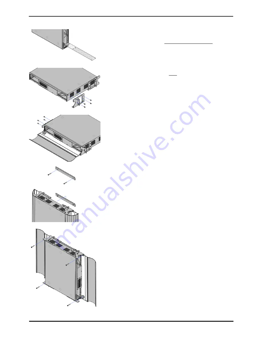
Figure 1
1. Shutdown the System
Ensure that the system has been shutdown and power has been removed
from all the units.
·
If mounting a control unit, you must wait at least 15 minutes after
removing the power cord before fitting the flame screen.
·
Shutdown the system using a shutdown command and then remove
power. Do not simply remove the power.
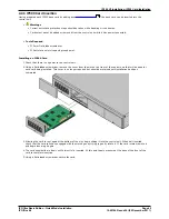
2. Fit the Flame Screen: Mandatory - Control Units Only (See Figure 1)
·
!
WARNING: The flame screen mesh must be fitted.
a. Remove the cards or blank slot covers from the left-hand and right-
hand slots.
b. Insert the flame screen into the bottom of the control unit, with the
two black plastic pegs at the front.
c. Press the two pegs through the air flow holes in the control unit
casing.
d. Check that the pegs have come through and have secured the flame
screen in place and that the screen is flush with the chassis.
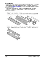
3. Attach Brackets on One Side (See Figure 2)
On one side of the unit, attach one pair of the metal brackets.
·
Only use the screws provided with the wall mounting kit for attaching
the metal brackets.
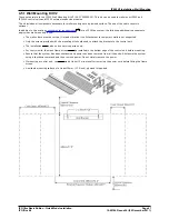
4. Attach the Cable Cover and Bracket (See Figure 3)
Use of the cable covers is optional. If not being used, simply attach the other
pair of brackets to the other side of the unit; otherwise:
a. Hook one of the cable covers into the leading hole of one of the metal
brackets.
b. Hook another bracket onto the other end of the cable cover and then
attach that bracket to the unit.
c. Repeat the process to attach the other cable cover to the unit.
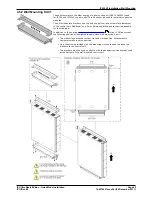
5. Fit the Wall Bracket (See Figure 4)
Using 2 of the screws provided with the kit, attach the wall bracket to the
plywood surface.
6. Place the Unit onto the Wall Bracket (See Figure 5)
Lift the unit onto the wall bracket. The two metal brackets at the top of the
unit hook over the top of the wall bracket.
7. Attach the Unit to the Wall Panel (See Figure 6)
a. Using the remaining 4 screws provided with the kit, fix the cover
brackets to the plywood surface.
b. Reinsert the base cards and blank slot covers.
Figure 2
Figure 3
Figure 4
Figure 5
Figure 6


