R5/R6/R7/R8si to Avaya Communication Manager
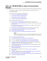
Task List: R5/R6/R7/R8si to Avaya Communication Manager
108
SI Installation and Upgrades
June 2004
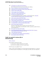
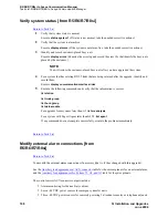
Verify system status [from R5/R6/R7/R8si]
Return to Task List
1
Verify that system status is normal.
Execute
status system 1
(If status is not normal, take the needed corrective actions.)
2
Verify that the system is alarm-free.
Execute
display alarms
(If the system is not alarm-free, take the needed corrective actions.)
3
Identify and record customer-placed busy-outs.
Execute
display errors
(Examine the error log and record the error 18s that identify the busy-outs
placed by the customer.)
NOTE:
You will restore the customer-placed busy-outs after you have upgraded the system.
4
For a system that has existing BX.25 links that are being retained after the upgrade: identify and
record them.
Execute
display communication-interface links
5
Execute the following commands and verify that the information is correct:
list station
list trunk-group
list hunt-group
list data-module
For upgrades from systems later than G1,
list ars analysis
For a system with Expert Agent later than G3V3,
list agent
If any command does not complete successfully, escalate the problem immediately.
Return to Task List
Modify external alarm connections [from
R5/R6/R7/R8si]
Return to Task List
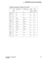
You modify the external alarm connections if necessary (that is, if they changed with this upgrade).
See the
Auxiliary lead appearances at AUX connector
table for the current pinouts for an external alarm,
and the
Auxiliary lead appearances for System 75, G1, and G3
table for the prior pinouts.
The control carrier AUX connector outputs include:
•
Alarm monitoring for the auxiliary cabinet.
•
Seven -48 VDC power sources for emergency transfer units.
•
Three -48 VDC power sources for remotely powering 3 attendant consoles or telephone adjuncts.


