Install Fiber Optic Cable Pass-Thru Kit for SCC1 (Single-Carrier) Cabinets
Install the fiber optic cable pass-thru kit (SCC1)
SI Installation and Upgrades
199
June 2004
3
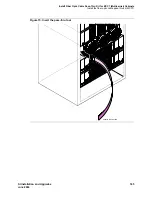
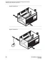
Slide the tool to the rear of the cabinet.
CAUTION:
Avoid bending fiber optic cables to a radius smaller than 1.5 inches (3.8 cm), to prevent
mechanical stress on the cables.
4
Attach the supplied fiber optic cable to the adapter.
5
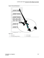
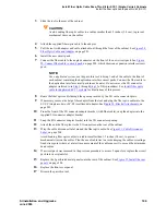
Pull the tool (with adapter and cable attached) out through the front of the cabinet. See
Figure 28,
Fiber Optic Cable and Adapter,
on page 201.
6
Install the new circuit pack.
7
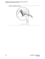
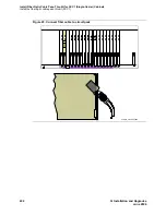
Connect the fiber cable to the angled connector on the front of the new circuit pack. See
Figure
29, Connect fiber cable to circuit pack,
on page 202, which shows an expansion interface circuit
pack.
NOTE:
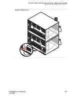
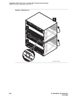
For a duplicated system, use the pass-thru tool to bring 1 end of the cable to the front of
each cabinet containing the duplication interface circuit packs. Connect the fiber cable to
the duplication interface circuit pack in each carrier. Do not remove the I/O connector
adaptor (referred to in
Step 9
through
Step 12
of this procedure). See
Install fiber optic
cable for duplicated SCC1 systems
for illustrations of this process.
8
Route the fiber optic cable through the opening vacated by the I/O cable connector plate.
9
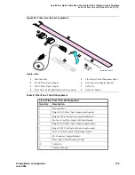
If necessary, remove the beige fiber adapter from the tool and plug the fiber optic cable into the
SC-SC (single-mode) or SC-ST (multimode) adapter. See
Figure 30, Bracket Attachments,
on
page 203.
10
From the front of the I/O connector adapter bracket (with fiber cable), snap the adapter into the
supplied I/O connector adapter bracket.
11
Snap the I/O connector adapter bracket into the I/O connector opening.
12
Attach the outside fiber plant to the I/O connector on the rear of the cabinet.
13
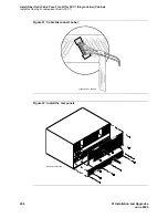
Wrap the cable disconnect label around the fiber optic cable. See
Figure 31, Cable Disconnect
Label,
on page 204.
Avoid bending fiber optic cables to a radius smaller than 1.5 inches (3.8 cm), to prevent
mechanical stress on the cables. Plan the use of cable ties to avoid crimping the cable or creating a
fixed stress point where, at a later time, movement of the cable causes it to exceed the minimum
bend radius.
14
If a circuit pack was removed in the previous procedure to access 2 open slots, replace the circuit
pack into its original slot.
15
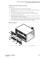
Replace the 2 perforated metal panels onto the rear of the cabinet. See
Figure 32, Install the rear
panels,
on page 204.
16
Replace the front cover panel.
17
Discard the pass-thru tool.

