System 75 Small-Cabinet to R8si (Blowback)
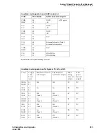
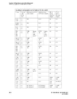
Task List: System 75 Small Cabinet to R8si
SI Installation and Upgrades
299
June 2004
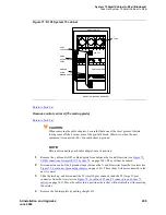
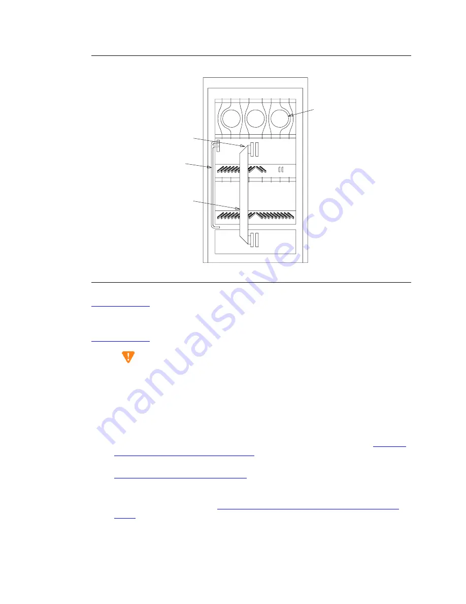
Figure 71: R1V3 System 75 cabinet
Return to Task List
Remove control carrier A [75 small upgrade]
Return to Task List
CAUTION:
When removing the cable adapters, be careful that none of the short pieces of shrink
tubing come off the 4 corner pins of the pin-field block. Otherwise, when the new
equipment is connected, -48 volts could short to ground.
NOTE:
Before disconnecting each cable adapter, note its position.
1
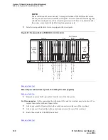
Remove the cable and AHF3 cable adapters from between the A and B carriers (see
Figure 72,
TDM connections for small R1V3 System 75,
on page 300). They will not be reused.
2
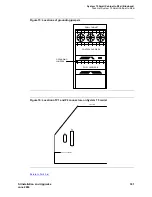
Disconnect one end of the 8 ground straps (between the A and B carriers) from the A carrier (see
Figure 73, Locations of grounding jumpers,
on page 301). These straps will be reconnected to the
new A carrier.
3
Slide the latch up, and disconnect the P1 (small 9-pin) connector and the P2 (large 37-pin)
connector from the A carrier (see
Figure 74, Location of P1 and P2 connectors on System 75
carrier,
on page 301). Move the cables into a position where they will not interfere with removing
the carrier.
4
Remove the fan trim plate by pulling straight off.
PORT CARRIER B
SMALL CABINET
FANS
RMSS OR
HCMR
RIBBON CABLE
RMSS
AC POWER
CORD
AHF4
CABLE ADAPTER
SLOT 07
REAR VIEW (COVERS REMOVED)


