System 75 Small-Cabinet to R8si (Blowback)
Task List: System 75 Small Cabinet to R8si
314
SI Installation and Upgrades
June 2004
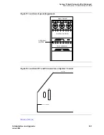
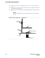
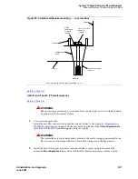
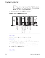
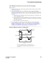
Figure 86: Locations of ground plate and cable clamps on single-carrier cabinet
Return to Task List
Power up and set date, time and daylight savings rule [75 small upgrade]
Return to Task List
CAUTION:
It may be necessary to reseat circuit packs. To prevent damage from static electricity,
always wear an Electromagnetic Compatibility (EMC) wrist strap (comcode 900698226)
when handling all system components.
NOTE:
To prevent unnecessary trouble tickets, do not enable the system alarms (Alarm
Origination feature) until all installation and administration procedures are completed.
1
Verify that the write switch on the Translation Flash-Memory Card (translation card) is positioned
down so the card can be written to. Install the R8si translation card into the TN794 circuit pack in
the direction indicated by the arrow on the label.
NOTE:
If the system is high or critical reliability, power up the EPN cabinet first, then the PPN
cabinet. Always power up the control cabinet last.
2
Power up the AC- or DC-powered system.
System
Steps
AC
1
Set the circuit breakers on the AC power panel to ON.
2
Set the cabinet circuit breakers to ON.
This starts the system initialization and test. All red LEDs
on the circuit packs go on and then off.
REAR VIEW
CABLE
CLAMPS
GROUND
PLATE


