Install and Connect MCC1 (Multicarrier) Cabinet
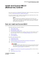
Task List: Install and Connect MCC1
SI Installation and Upgrades
331
June 2004
•
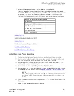
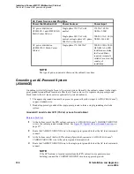
Model 15A Announcement System — see the table for a list of equipment.
The BLD1 circuit pack provides 8 channels with up to 20 seconds of recording time on each
channel. The BLD2 circuit pack provides 8 channels with up to 40 seconds of recording time on
each channel. Each chassis can be populated with any combination of 2 BLD circuit packs.
The Model 15A Announcement System is FCC registered and does not require a voice coupler.
Return to Task List
Install Earthquake Protection for MCC1
Return to Task List
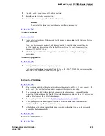
Use the correct procedure for your installation:
Install Concrete Floor Mounting
Install Raised Computer Floor Mounting
Install Concrete Floor Mounting
1
Position the cabinet in the exact position it is to occupy when the installation is complete.
2
Insert a pencil or marker through the holes previously occupied by the carriage bolts (front and
rear) in the bottom of the cabinet and mark the floor directly beneath each hole.
3
Roll the cabinet out of the way and drill four 1/2-in. (1.27 cm) diameter holes about 1.5 in. (3.8
cm) deep at the locations marked in Step 2.
4
Insert concrete floor anchors (STARR part number 3425) into the holes.
5
Roll the cabinet back into place and align the cabinet holes over the concrete floor anchors.Adjust
the leveling legs until the cabinet is level. See
Earthquake Mounting — Raised Computer Floor
.
NOTE:
If the system is supplied with cable ductwork, the cabinets must be level from front to rear
and from side to side. They must be square with respect to each other to within ±1/8-in.
(0.3 cm).
6
Secure the cabinet to the floor with the 4 supplied 3/8-16 x 4.5-in. (11.4 cm) bolts and four 3/8-in.
flat washers.
7
Repeat this procedure for each cabinet to be installed.
Model 15A Announcement Equipment
Description
1 chassis and 1 BLD1 circuit pack
1 BLD1 circuit pack
1 chassis and 1 BLD2 circuit pack
1 BLD2 circuit pack
1 remote record module


