Install and Connect MCC1 (Multicarrier) Cabinet
Task List: Connect DC Power and Ground
348
SI Installation and Upgrades
June 2004
3
Tie wrap the ground wire to the inside wiring cable.
NOTE:
The ground wires are connected to the CBC as instructed in
Install Telecommunications
Cabling
.
Return to Task List
Connect DC Battery and Power Cabinet Grounds
Return to Task List
NOTE:
The wire in the next step must be sized for a maximum voltage drop of 0.5 VDC in each
leg of the DC distribution. In this example 1 AWG is used.
1
Measure and cut a minimum of a 1 AWG (#70) (44 mm
2
) wire long enough to reach between the
ground connection terminal in the DC Battery Cabinet and the Ground Discharge Bar in the DC
Power Cabinet. See
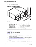
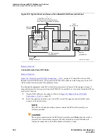
Figure 95, Typical Power and Ground for a DC-Powered Cabinet,
on page
344.
2
Crimp terminal lugs on each end of the wire. Terminal lugs are furnished as part of D-181895, Kit
of Parts.
3
At the DC Power Cabinet, connect the wire to the Ground Discharge Bar.
4
Route the wire through 1 of the holes in the side of the cabinets and terminate it on the Ground
Connection Terminal in the DC Battery Cabinet.
Return to Task List
Connect DC Power Cabinet Approved Ground
Return to Task List
NOTE:
The wire must be at least as large as the largest distribution wire in the system (required by
UL). In this example 1 AWG is used.
1
At the DC Power Cabinet, connect a 1 AWG (#70) (44 mm
2
) ground wire to the Ground
Discharge Bar. See
Figure 95, Typical Power and Ground for a DC-Powered Cabinet,
on page
344.
2
Route the ground wire out of the cabinet and terminate it on the approved ground. The approved
ground must be identified with a grounding tag (FORM 15657NR or equivalent). See
Approved
Grounds
.
Return to Task List


