Install and Connect MCC1 (Multicarrier) Cabinet
Task List: Connect DC Power and Ground
SI Installation and Upgrades
351
June 2004
6
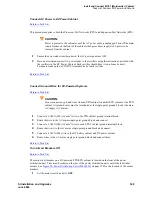
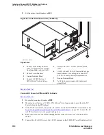
Connect the -48 volt RTN wire to the -48RTN terminal on the J58890CF Power Distribution Unit
terminal block.
7
Repeat Steps 2 through 6 for each EPN and Auxiliary cabinet in the system.
Return to Task List
Connect DC Battery Cabinet to DC Power Cabinet
Return to Task List
NOTE:
The wire in the next step must be sized for a maximum voltage drop of 0.5 VDC in each
leg of the DC distribution. In this example 1 AWG is used.
1
Turn off the main circuit breaker on the DC Battery Cabinet.
2
Turn off the main circuit breaker on the DC Power Cabinet.
3
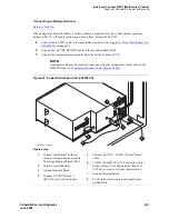
Measure and cut a 6 AWG (#40) (16 mm
2
) wire long enough to reach from the DC Battery
Cabinet’s -48 Volt DC terminal to a DC OUTPUT distribution bus on the DC Power Cabinet.
4
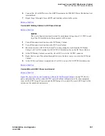
At the DC Battery Cabinet, connect the -48 volt DC wire to the -48 VDC connector.
5
Route the wire out of the cabinet through the hole in the lower rear cover and to the DC Power
Cabinet.
6
At the DC Power Cabinet, terminate the -48 volt DC wire on a DC OUTPUT distribution bus.
Return to Task List
Connect Mixed AC/DC Power and Ground
Return to Task List
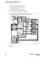
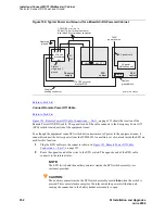
Figure 100, Typical Power and Ground for a Mixed AC/DC-Powered Cabinet,
on page 352 shows a
power and ground layout for a mixed AC/DC-powered cabinet configuration in the same equipment
room with the PPN being DC powered and the EPN being AC powered. If a second EPN is part of the
system, use the same basic connections.


